21
ecoTEC plus 937 installation and maintenance manual
00
2
0
0
3
997
5_00
10 2
006
180
60/100
140
195 ( )
40
60/100
17
3
2
7
6 ( )
80/125
80/125
(Art.-Nr. 303210)
(Art.-Nr. 303910)
5
5
223
25
6
A
A
25
A
A
A
117
6
450
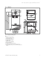
Fig. 4.2 Assembly template
4.5 Flue
exit
• If using rear flue mark the position of the air/flue duct
and its circumference.
• Remove the assembly template from the wall.
• If necessary cut the aperture in the wall for the flue
pipe.
Other flue options
Instructions concerning other flue pipe systems, for
example, vertical flues, flue pipes to the side of the
boiler and the use of additional elbows etc. are listed in
the installation instructions for the flue pipe included
with the combi boiler.
4.6
Installation of the flue gas system
• Install the flue gas system (observe the separate
installation instructions for the flue pipe).
4.7
Fitting the appliance hanging bracket
1
3
2
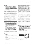
Fig. 4.3 Shift load storage tank with hanging bracket
• Fix the hanging bracket (
1
) to the wall using the plugs
and screws (
2
) provided with the appliance.
• Lift the shift load storage tank out of the packaging
(see Section 3.4).
• Lift the shift load storage tank (
3
) onto the wall so
that it is located slightly above the hanging bracket (
1
).
• Slowly lower the shift load storage tank onto the
hanging bracket so that the installation carrier on the
rear of the unit fully engages in the hanging bracket.
Note:
If the appliance is to be fitted in a timber
framed building ensure that the hanging bracket
is secured to a substantial part of the timber
frame capable of taking the full weight of the
appliance.
Sequence of operations during installation 4


