Installation 5
0020230756_00 0020230738 Installation instructions
13
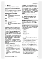
Danger!
Risk of material damage caused by over-
tightening the thread
The reducing flange is pre-installed with a
specific torque on the thread of the electrical
immersion heater, meaning that the drilling
hole pattern and immersion heaters are at the
ideal distance from each other. If you further
tighten the reducing flange on the thread
for the electrical immersion heater, this may
damage the thread.
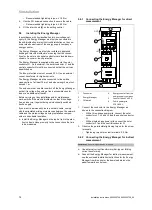
▶
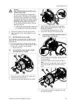
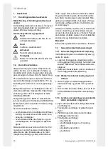
Install the electrical immersion heater with
pre-installed reducing flange as supplied.
2.
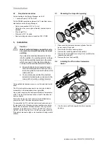
Install the PV electrical immersion heater as shown.
3.
Tighten the screws on the reducing flange in a cross-
wise pattern.
5.3
Establishing the power supply
The external power supply cable must be earthed and con-
nected with the correct polarity and in accordance with the
valid regulations.
▶
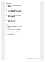
For the wired power supply, install an all-pole partition
from the network with a contact opening width of at least
3 mm per pole (e.g. fuses or power switches).
–
16 A fuse protection
5.4
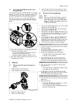
Connecting the power supply to the PV
electrical immersion heater
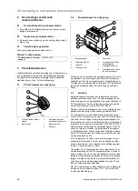
1
2
4
3
1.
Remove the rotary knob
(4)
from the setting control.
2.
Remove the four hex screws
(3)
.
3.
Remove the connector housing
(1)
and the seal
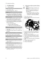
(2)
.
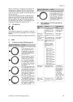
L1 N
1
2
3
4.
Guide the cable
(2)
through the power supply open-
ing and into the housing, and secure it using the PG
screwed connection
(1)
.
–
Recommended tightening torque:
≤
6.0 Nm
5.
Connect the conductors to the terminal block
(3)
.
5.5
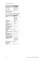
Connecting the RS485 data cable to the PV
electrical immersion heater
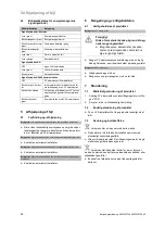
C
(G
N
D
)
BA
D
1
2
1.
Guide the RS485 cable through the opening in the con-
nector housing
(1)
.
2.
Connect the conductors to the terminal block
(2)
, as
shown.
3.
Allow one side of the cable shield to make contact with
GND (C) on the side of the PV electrical immersion
heater.
1
2
4
3
4.
Fit the seal
(2)
and connector housing
(1)
, and install
the four hex screws
(3)
.


