


32
MKHF | MKHS
Montageanleitung
Mounting instructions
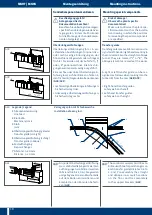
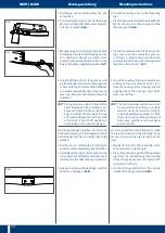
Zur Montage des Ausbauteilstücks wie
folgt vorgehen:
▸ Ausbauteilstück an der gewünschten Po-
sition oder entsprechend Verlegungsplan
an einer vorhandenen Konsole anbringen
▸ Stromschienenverbindung herstellen
(Muttern lösen, Gewindestift M6 mit max
2 Nm anziehen, Mutter mit 5 Nm kontern)
▸ Stoßabdeckkappen montieren (siehe
Seite 13)
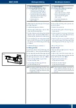
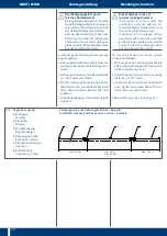
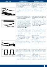
Revisionsteilstück
Das Revisionsteilstück lässt sich ganz ein-
fach aus einer Anlage demontieren und
wieder einbauen
Durch Öffnen der 3 Abdeckkappenpaare
lassen sich die beiden Gehäusehälften
zueinander schieben Dadurch entsteht
an jedem Ende der nötige Freiraum um die
gelösten Schraubverbinder komplett auf
das Kupfer zu schieben (
G63
)
To mount the extension section, please
proceed as follows:
▸ Attach the extension section in the desi-
red position or acc to the installation
drawing to an existing support bracket
▸ Create conductor rail connection (loosen
nuts, tighten setscrews M6 with max
2 Nm, lock nuts with 5 Nm)
▸ Mount the joint caps (see page 13)
Maintenance section
Maintenance sections can be easily and
quickly disassembled or reinstalled at an
existing installation
By opening the 3 joint caps the two
housing sections can be pushed together
Now there is enough space at each end
of the section to push the bolted joints
completely onto the copper (
G63
)
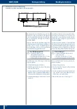
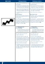
B
Lebensgefahr durch
Stromschlag!
Die Schleifleitung muss vor der De-
montage des Revisionsteilstücks
spannungsfrei geschaltet werden
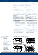
Demontage des Revisionsteilstücks
▸ Kappen entfernen (
1
)
▸ Teilstücke zueinander schieben (
2
)
▸ Sicherungsmuttern und Gewindestifte
der Schraubverbinder (
3
) lösen und die
Schraubverbinder dann komplett auf das
Kupfer des Revisionsteilstücks schieben
▸ Revisionsteilstück herausnehmen
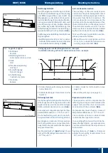
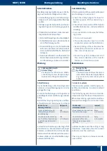
Montage des Revisionsteilstücks
▸ Die Montage des Revisionsteilstücks
erfolgt in umgekehrter Reihenfolge
Beachten Sie die Montagehinweise für
die Stöße in der jeweiligen Standard-
Montageanleitung
B
Danger to life
by electric shock!
The conductor systems must be dis-
connected from the power supply
before disassembling the mainte-
nance section
Disassembly Instructions
▸ Remove joint caps (
1
)
▸ Push PVC sections together (
2
)
▸ Loosen lock nuts and threaded bolts at
the bolted joint splices (
3
) and push joint
slices fully onto the copper conductors
of the maintenance section
▸ Lift out entire maintenance section
Installation Instruction
▸ To install the maintenance section, rever-
se above sequence Be certain to follow
the bolted joint installation instructions
pertaining to KBH and MKH systems
1
1
1
1
1
1
3
2
2
3
G63