Troubleshooting
90
Ver.3 29/06/07
Unintentional very slow unfold-
ing of retracted bout marker(s)!
- Check that the indicator lamp of the bout marker is not
lit on the Control Station.
- Check that the electric valve (A) or (B) of the bout
marker does not receive current. See ”
- Replace the electric valve of the right bout marker
with the electric valve of the left bout marker, and
vice versa.
If the fault then appears on the other side, it is caused
by a defective electric valve.
If the fault remains, it is likely that the hydraulic ram
of the bout marker is defective.
- Disassemble the electric valve and check whether it is
contaminated and that the outer seals of the valve are
intact and free from damage.
NOTE!
First lower the drill to the ground and depres-
surize the system!
- Check that the bout marker ram does not leak on the
outside and inside. For seal replacement, see
Changing the seals on the hydraulic rams” on page
80.
- If the bout marker unfolds when the machine is
parked, set the stopper and make sure the machine
rests on its wheels, discs and support leg. Use the
safety cotter pins.
Automatic switching of the bout
marker and/or tramlining does
not occur!
- Is the Control Station set to auto advancing?
- Has the bout marker function selector been set to the
alternating position? The indicator lamp in the button
should light.
- Has the correct tramlining programme been selected?
- Has the low-lift switch been correctly adjusted? See
”2.26 Adjusting Low lift height” on page 59.
When
the low-lift position is reached, a signal is output to
engage auto advancing.
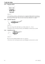
- Check whether the low-lift switch mounting device is
bent, whether it has been caught in an incorrect posi-
tion or whether the magnetic sensor is damaged. Is the
magnet been broken or is it loose? Also check for a
possible severed cable or a short-circuit.
The drill can be raised although
the lift stop is engaged!
- Check whether the magnetic valve (C) on the valve
block receives current. See
Hydraulic electric valves
under ”
5.1.3 Hydraulic electric valves” on page 87.
- Check the low-lift switch as explained above.
If the lift stop valve does not receive
current:
- See ”
5.1.1 Electric fault” on page 86.
If the lift stop valve receives cur-
rent:
- See ”
Summary of Contents for RAPID RDA S Series
Page 1: ...Ver 3 29 06 07 900236 dk Instruktioner S maskine RAPID serie RDA 600 800 S Nr 12 800 14 799...
Page 2: ...2 Ver 3 29 06 07...
Page 17: ...RDA 600 800 S Ver 3 29 06 07 17...
Page 20: ...Instructions and settings 20 Ver 3 29 06 07 2 8 Horizontal alignment Figure 2 18 A E C D B...
Page 71: ...RDA 600 800 S Ver 3 29 06 07 71 Figure 4 4...
Page 104: ...Appendices 104 Ver 3 29 06 07 6 3 2 Hydraulic diagram RDA 800 S Figure 6 2 444639...
Page 116: ...Appendices 116 Ver 3 29 06 07...
Page 117: ......


