WallVIEW CCU H700
WallVIEW CCU H700 Installation and User Guide 341-717 Rev. C Page 2 of 12
INFORMATION
For RS-232 control information, please see the full-length Technical Manual for the Sony BRC-H700. This
manual can be found either on the Vaddio or Sony website. Vaddio has also prepared a number of
TechNotes, specifications and drawings designed to inform and educate integrators on the value and the
specific uses of Vaddio products.
UNPACKING
Carefully remove and identify the following parts for the WallVIEW CCU H700 system:
•
One (1) - Sony BRC-H700 High Definition PTZ Camera, IR Remote & Manual
•
One (1) - Vaddio EZCamera Interface Module CCU (EZIM CCU)
•
One (1) - Vaddio EZIM CCU to HD Break Out Cable
•
One (1) - Vaddio Quick-Connect CCU Universal (1-RU Rack Mountable)
•
One (1) - Vaddio Thin Profile Wall Mount
•
One (1) - EZCamera Control Adapter (RJ-45 to DB-9)
•
One (1) - 36V PowerRite Power Supply with AC Cord Set
•
Mounting
Hardware
•
Vaddio
Manual
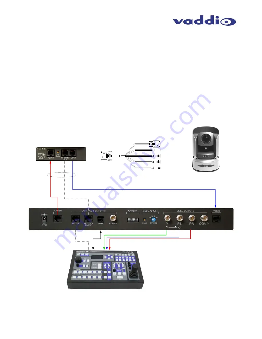
Wiring Diagram Example:
CAT-5 Cables
up to 500’
HD Break-out
Cable
EZIM CCU
Power
RS-232
HD Video on CAT-5
RS-232 Tally
ProductionVIEW HD
HD VIDEO OUT (Y, Pb, Pr)
RS-232 IN
SD VIDEO OUT (SD card required)
G/L
POWER
Quick-Connect CCU
BRC-H700 Camera, Wall Mount
with EZIM CCU (behind camera)
Component HD
Figure 2:
The Quick-Connect CCU System uses a Cat. 5 (all 4-pairs) for power to ensure the motors receive the required
current to operate properly. The Video Cat. 5 cable uses all four pairs for video. The RS-232 Cat. 5 provides communication
to the camera for CCU and PTZ control and G/L (where applicable) to the camera. These Cat. 5 cables can be run up to
500’ (152.4m). See Appendix 1 for wiring and pin-out information. NOTE: A direct RS-232 Cat. 5 cable is required for each
Quick-Connect CCU and camera. Daisy-Chain configurations are not supported.
+
G


