CeilingVIEW HD
Vaddio CeilingVIEW HD CCU Installation and User Guide - Document 341-768 Rev. A
Page 4 of 16
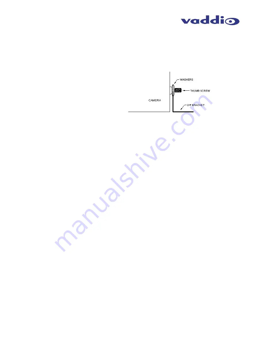
6. Using the supplied thumbscrews and washers, attach the support rails to the CeilingVIEW camera
(see Figure 4). Place rail edge between two washers and tighten thumbscrew securely. Repeat for
the other rail.
NOTE:
The thumbscrew sits on top of the rail, not through the holes on the rail.
7. Two CAT-5 cables (plenum rated as building codes dictate) are run from the ceiling location where the
camera is mounted, to where the Quick-Connect Box is located near the main rack or head-end
equipment. Either HD analog component (Y, Pb, Pr) or SD composite and Y/C are active.
Connections on the CeilingVIEW HD CCU are shown in Figure 5.
NOTE:
If you are terminating your own CAT-5 cables, make sure to test all cables with a continuity
tester to confirm proper pin-outs.
8. Next, connect the Power/Video CAT-5 cable from the Quick-Connect CV HD/SD box to the CAT-5
cable that is connected to the Power-Video port on the Camera Enclosure in the ceiling (see Figure 5).
The Quick-Connect CV HD/SD provides power to the camera, as well as delivers video back from the
camera module. Note: The Quick-Connect CV HD/SD uses a 24VDC power supply and the Quick-
Connect CCU uses a 36VDC power supply.
9. For RS-232 control, connect the CAT-5 cable to the Camera Enclosure, and then the other end of the
CAT-5 cable to the RS-232 output on the Quick-Connect CCU (see Figure 5). If there is an external
RS-232 controller (e.g. Vaddio’s ProductionVIEW HD, or a control system such as Crestron or AMX,
etc.) then connect a CAT-5 cable between that external controller and the RS-232 Input on the back of
the Quick-Connect CCU. An RJ-45 to DB-9 connector is supplied for DB-9 RS-232 ports.
10. NOTE: The Quick-Connect CCU will only send RS-232 commands
to the camera’s image sensor. All
zoom and zoom preset commands are handled by an external controller or IR remote controls that are
compatible with CeilingVIEW HD. Pressing CCU Control on the front panel of the CCU allows the
user to adjust all of the knobs and controls on the front panel. Pressing CCU control again, allows RS-
232 commands from an external control system (e.g. ProductionVIEW HD, AMX, Crestron, etc.) to
pass through to the Camera Module.
11. To finish the installation, the camera and ceiling tile should be carefully replaced in the suspended
ceiling at this time. Carefully move the trim ring into position on the bottom of the ceiling tile and
secure with the two supplied white screws.
12. With the CAT-5 cabling connected to the proper ports at both the Camera Enclosure and Quick-
Connect CV HD/SD interface, review the dip switch settings (Figure 6) and set the camera to output
the desired signal. Connect the Vaddio PowerRite power supply. Plug the AC cord into an outlet.
The camera zoom will home into position and the video output (either HD component or SD composite
and Y/C as selected with the dip switch settings) signals will be live and viewable after the camera is
fully initialized. To change the output resolution or any dip switch setting, first unplug the power
supply, change the dipswitch setting and re-power the Quick-Connect CV HD/SD. If using a Polycom
or TANDBERG IR Remote, set dip switches 1 & 2 accordingly to allow momentary laser pointer on the
Tilt Down command.
NOTE:
Use of a power supply other than the provided Vaddio power supply for this device will void
the warranty and may cause camera and equipment damage. Make sure that the proper power
supply is connected to the Quick-Connect boxes – they are different voltages.
Figure 4:
Side View of CeilingVIEW
HD with Tile Support
Brace placement


