ADD-A-Cam PRO
Add-A-Cam PRO - Document 341-592 Rev. C
Page 7 of 13
•
Step 6:
Power Connection
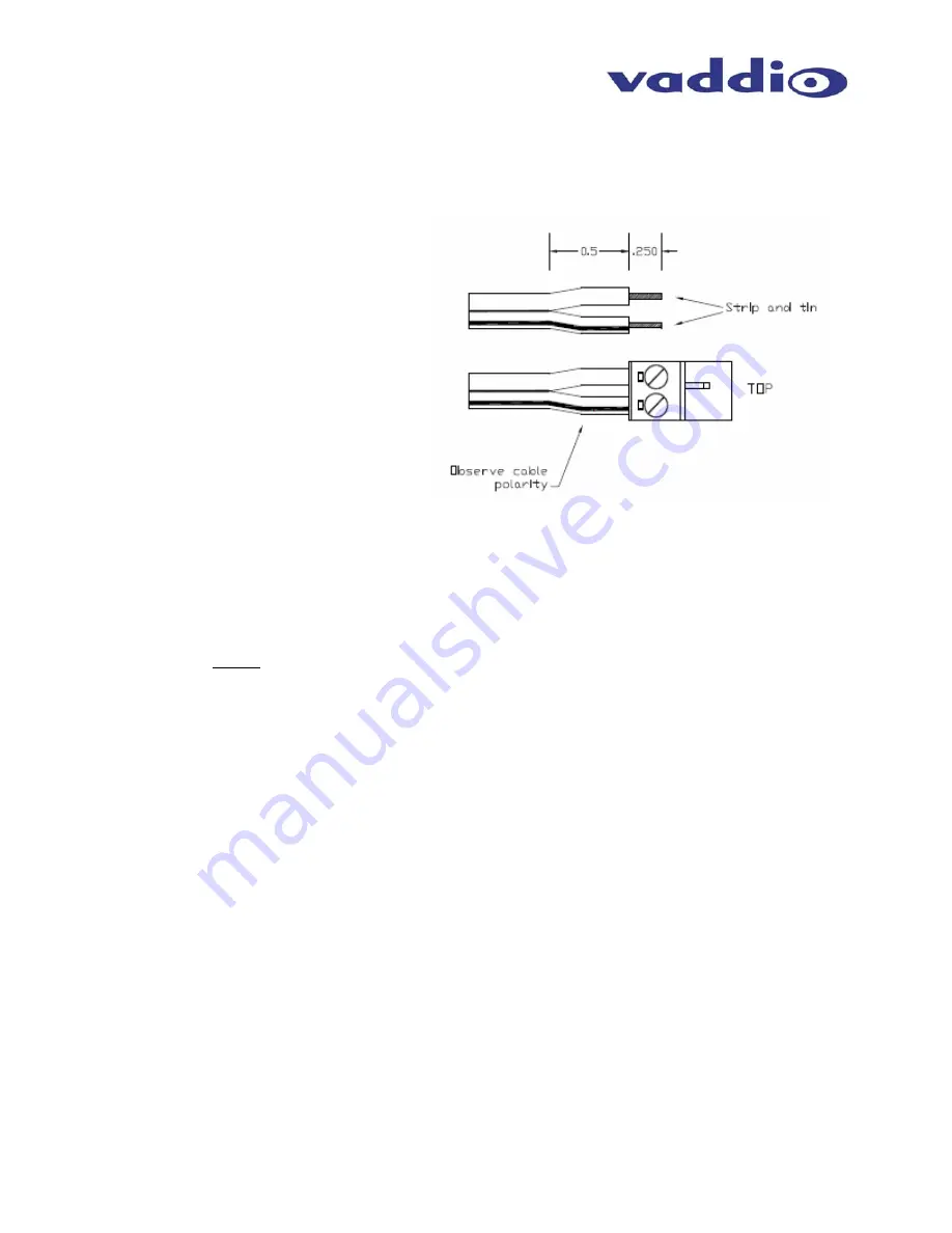
Remove the DC-920 power adapter supplied with your Canon camcorder. Connect the
adapter to the camera. Follow the cable from the adapter down to the Power port on the
Shoe. Cut the cable to an appropriate length and terminate the cable ends to the supplied
Phoenix type (2-pin spring cage) connector according to the example below.
•
Step 7:
Cat. 5 Connections
Power:
Connect the Power/Control Cat. 5 between the Quick-Connect PRO and the
EZCamera PRO Shoe. Leave enough slack for adjustments to the cabling to ensure full
range of motion of the Shoe on a tripod or on a pan/tilt head.
Video:
Connect the Video Cat. 5 between the Quick-Connect PRO and the EZCamera PRO
Shoe. Again, leave enough slack for adjustments to the cabling to ensure full range of
motion of the Shoe on a tripod or on a pan/tilt head.
Verify
:
Verify the connections - inserting the Cat. 5 cable, or an incorrectly terminated
cable into the wrong RJ-45 jack may cause damage to the camera system and will
void the warranty
Pan/Tilt
: If using the Pan/Tilt PRO pan/tilt head, connect the Pan/Tilt RJ-45 on the
EZCamera Shoe to the RJ-45 with a short Cat. 5 patch cable (straight through).
Control
: Connect a Cat. 5 cable from the LINK port on the Quick-Connect PRO to a camera
control port of a ProductionVIEW series camera control console.
•
Step 8: Initial Power Up
Connect the 36 VDC Power Supply to the Quick-Connect PRO. Power will travel down the
Power/Control Cat. 5 cable to the Shoe, powering the camera. Follow the instructions in the
camcorder manual and switch the camera on to the appropriate setting.
•
If the System is communicating, the Green Power LED will be on a solid green
•
If the Power/Control Cat. 5 is not connected correctly, or has a cabling problem, the
Green LED will blink in one-second intervals. If the Green LED blinks, there is a
cabling issue that requires resolution.
•
To ensure proper continuity of control and operation of the cameras, the RS-232
controller (control system or joystick) should be powered on after the camera.
•
Step 9:
Completing the Installation
After the system is powered up and the solid Green LED is verifying system communication,
turn on the ProductionVIEW series camera controller. The ProductionVIEW will auto-
recognize and load the control codes for the Add-A-Cam system. The ProductionVIEW
controller will control the Pan/Tilt PRO pan/tilt head and control the Zoom function of the
camcorder lens through the LANC connection.
Figure 9:
Power Connection
Connect the stripped cable with the
screw terminal on the right side of the
connector with the screws pointed up.
This diagram is for Canon XL-2, XH-A1,
XH-G1 and XL-H1 camcorders. Refer
to the owner’s manual for appropriate
termination for any other camcorders.


