background image

Squiggle Video Whiteboard Kit


Squiggle Manual 342-0172 Rev. B 


               Page 6 of 16 

Installation Step by Step: 

 
Before Installing: 

  Keep other IR or ultrasonic devices and reflective surfaces away from the whiteboard location.  

  Since Squiggle is being installed next to an existing whiteboard, pull out the tape measure and prepare to 

measure precise positions for the location of the EZTub and Digital Control Panel.  Typically, the Squiggle 
Quick-Connect Interface is located at the head-end, so we’ll make that assumption here too. 


Step 1: 

Measure the existing whiteboard.  Squiggle is always 
mounted on the left side and center of the whiteboard.  
The center of the Digital Control Panel, not the EZTub, 
must be centered on the left side of the white board.   
 
The system is shipped with the EZTub and three (3) ¼” 
thick wall spacers (right) to allow the EZTub and Digital 
Control Panel to sit flush with the whiteboard surface. 
 
In our mounting example, the whiteboard is a 3’ x 5’ 
and sits about 1” out from the wall.  Make a mark at 1.5’ 
on the left side of the whiteboard surface and this will 
be where the center blue IR receiver (with the Vaddio 
Logo) will be aligned. 


Step 2: 

Determine the required number of wall spacers to raise the 
EZTub and Digital Control Panel to the correct height to be even 
with the surface of the whiteboard.  In this example, the two ¼” 
spacers and the EZTub will provide the 1” height needed.   
 

Step 3: 

Stack the EZTub and two (2) spacers.  Hold them to the left side 
of the whiteboard and center the opening for the Digital Control 
Panel on the mark that was made on the whiteboard.  Snap in 
the Digital Control Panel and adjust the height so the center blue 
dot is on the center mark.  Using the removal tool, remove the 
Digital Control Panel and mark the position of the screws.  The 
EZTub has two keyhole slots and the spacers have oval slotted 
screw holes.  While still holding the EZTub and Spacers against 
the left side of the whiteboard, make two marks on the wall at the 
top of the keyhole slots on the EZTub.   
 

Step 4: 

Install the two (2) provided spiral wall anchors, or installer’s 
preferred anchors at these marks. 
 

Step 5: 

Route the Cat-5e cable from the Squiggle Quick-Connect 
Interface and decide if the cabling will run inside the wall behind 
the EZTub or will be surface mounted.  Each Wall Spacer (see 
illustration on right) has a cable pass-thru at the bottom to allow 
the Cat-5e cable to pass through the wall to the RJ-45 connector 
on the back of the EZTub connector. 


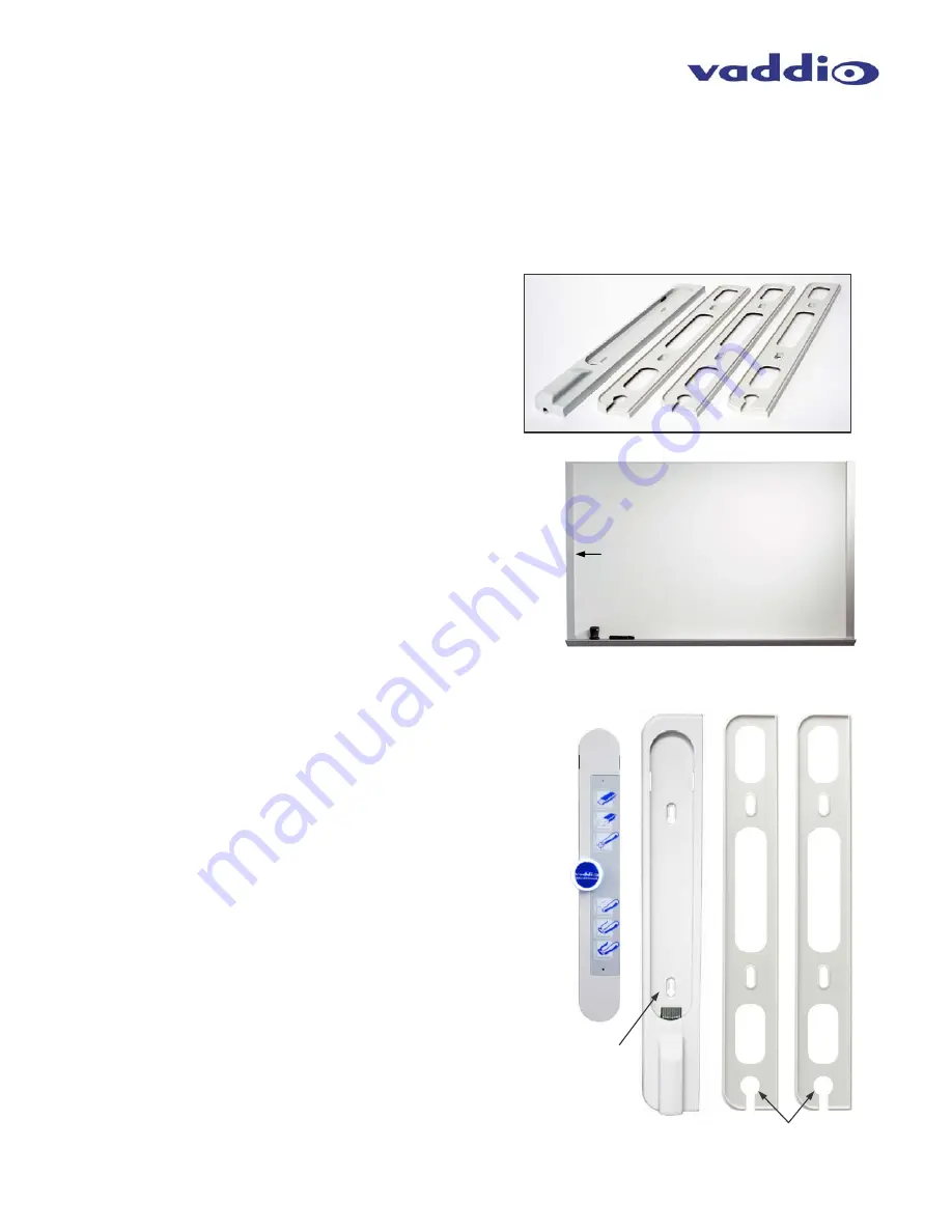
Center, Left Side of Whiteboard 

Digital Control Panel, EZTub and two (2) Wall Spacers 
(left to right below) 

Cable pass-thru into 
wall behind EZTub 

Keyhole 
Slot 

EZTub and three (3) all Spacers 

Any Whiteboard 

Summary of Contents for 999-5441-000

Page 1: ...ment Number 342 0172 Rev B Installation and User Guide V VA AD DD DI IO O S SQ QU UI IG GG GL LE E V VI ID DE EO O W WH HI IT TE EB BO OA AR RD D K KI IT T Make Any Whiteboard into a Video Whiteboard...

Page 2: ...Squiggle Video Whiteboard Kit Squiggle Manual 342 0172 Rev B Page 2 of 16 Inside Front Cover blank...

Page 3: ...the USA the Squiggle simply makes any whiteboard into a video whiteboard and further redefines the concept of the electronic whiteboard for presentation videoconferencing distance learning media retr...

Page 4: ...g this button will save a copy of what has been drawn on the whiteboard as a 1280x720 JPEG image 3 Erase Button To erase all content on the whiteboard video output simply press this button Pressing th...

Page 5: ...g 3 Ethernet on RJ 45 Ethernet port is reserved for future use and not active at this time 4 Settings The Quick Connect has a 5 position dip switch for setting HD or SD resolution refresh rate test ba...

Page 6: ...Panel to the correct height to be even with the surface of the whiteboard In this example the two spacers and the EZTub will provide the 1 height needed Step 3 Stack the EZTub and two 2 spacers Hold...

Page 7: ...or EZ type RJ 45 connectors These pass thru type connectors do not work well for professional installations and can be the cause of intermittent connections For best results please use standard RJ 45...

Page 8: ...P SW2 UP SW5 UP SD 480i NTSC Color Bars Off SW1 DN SW2 UP SW5 UP HD 720p 50 Color Bars Off SW1 UP SW2 DN SW5 UP SD 576i PAL Color Bars Off SW1 DN SW2 DN SW5 UP Notes Default Position for all Switches...

Page 9: ...nd polarity of the pen sleeve batteries installed If there is an unintentional mistake during calibration simply touch the calibration button again to stop the process To restart calibration touch the...

Page 10: ...ng a session and then put the marker cap on the marker holder Loose clothing such as cuffs or puffy pirate sleeves can block the pen transmitters and cause drop outs and less than acceptable results P...

Page 11: ...22m x 2 03m Squiggle Quick Connect Interface Connectors Power Connector 5 5mm OD x 2 5mm ID Whiteboard RJ 45 Supplies power and Serial Data to Whiteboard Digital Control Panel Ethernet RJ 45 Reserved...

Page 12: ...thority to operate this equipment ICES 003 Compliance This digital apparatus does not exceed the Class A limits for radio noise emissions from digital apparatus set out in the Radio Interference Regul...

Page 13: ...ite your assigned RMA number on the shipping label when returning the product All returns are subject to a restocking fee without exception see warranty policies at vaddio com Voided Warranty The warr...

Page 14: ...Squiggle Video Whiteboard Kit Squiggle Manual 342 0172 Rev B Page 14 of 16 Squiggle Notes...

Page 15: ...Squiggle Video Whiteboard Kit Squiggle Manual 342 0172 Rev B Page 15 of 16 Inside Back Cover blank...

Page 16: ...1 4464 www vaddio com 2011 Vaddio All Rights Reserved Reproduction in whole or in part without written permission is prohibited Specifications and pricing are subject to change without notice Vaddio Q...

Reviews: