background image

page 49 of 58

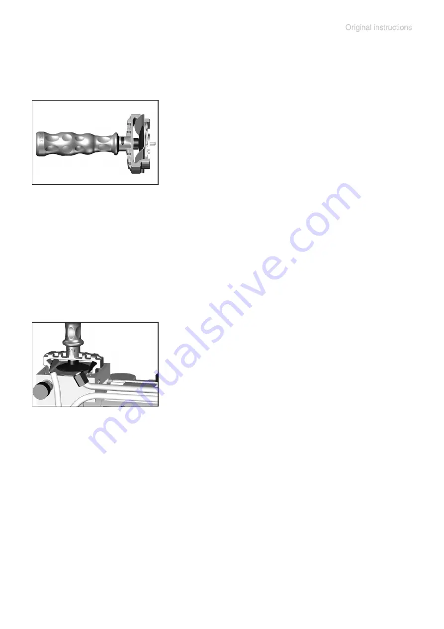
 Position new diaphragm between dia-

phragm clamping disc with square head 

screw and diaphragm support disc.

+

 Note: Position diaphragm with pale side 

towards diaphragm clamping disc (facing 

pump chamber).

+

 Make sure that the square head screw of the diaphragm clamping disc 

is correctly seated in the guide hole of the diaphragm support disc.

 Lift the diaphragm at the side. Place the diaphragm carefully together 

with diaphragm clamping disc and diaphragm support disc in the dia-

phragm key.

+

 Avoid damage of the diaphragm: Do not excessively bend or crease  

the diaphragm.

+

 Assemble the original number of washers 

between diaphragm support disc and con-

necting rod.

 Screw diaphragm clamping disc , dia-

phragm, diaphragm support disc, and wash-

ers to connecting rod. 

 Optimum torque for the diaphragm support disc: 4.4 ft

.

lb

(6 Nm), it is 

recommended to use a torque wrench. Attach torque wrench to dia-

phragm key (hexagonal bolt 6 mm wide). 

  Note: Never use the diaphragm key with any additional tools like tongs 

or Allen keys without appropriate torque limitation. 

+

 Too few washers: The pump will not attain vacuum specification. Too 

many washers: Diaphragm clamping disc will hit head cover, causing 

noisy operation and possibly causing the pump to seize up.

Summary of Contents for RC 6

Page 1: ...page 1 of 58 Chemistry HYBRID pump RC 6 Instructions for use Technology for Vacuum Systems...

Page 2: ...s Any faults even those which occur rarely are identified and can be eliminated immediately After completion of the endurance run every pump is tested and must achieve specifications before shipment W...

Page 3: ...ing operation 27 Important notes regarding the use of gas ballast 30 Operating the pump with condensate in the catchpots 32 Pumping chemically aggressive or toxic gases and vapors 33 Shutdown 34 Oil c...

Page 4: ...page 4 of 58 Repair Maintenance Return Calibration 53 Warranty 55 Health and safety clearance form 56 EC Declaration of Conformity of the Machinery 57...

Page 5: ...he pump and the pumped substances VACUUBRAND disclaims any liability for inappropri ate use of these pumps and for damage from failure to follow instructions contained in this manual This manual is on...

Page 6: ...oderate injury NOTICE is used to address practices not related to personal injury Caution Hot surface Disconnect equipment from AC power NOTICE Formatting used in this manual Note The signal word pane...

Page 7: ...claims for those deficiencies Replace the protective caps if the equipment is not used immediately Store the equipment in dry and non corrosive conditions see also Technical data pg 19 Do not use any...

Page 8: ...g Make sure ventilation is adequate to maintain recom mended operating temperature Install an external au tomatic ventilation system if necessary If pumping hot process gases make sure that the maximu...

Page 9: ...valve at the outlet Do not permit any uncontrolled pressurizing Make sure that the exhaust tubing cannot become blocked If there is an exhaust isolation valve make sure that you cannot operate the eq...

Page 10: ...gents are pumped Take adequate precautions when handling pump flu ids lubricants and solvents Use appropriate protec tive clothing safety goggles and protective gloves to avoid excessive contact with...

Page 11: ...om cold environment into a room prior to operation Notice if there is water condensation on cold surfaces Comply with all applicable and relevant safety require ments regulations and guidelines Implem...

Page 12: ...poten tially explosive atmospheres The pumps are not suitable to pump any of the sub stances listed below Do not pump unstable substances substances which react explosively under impact mechanical st...

Page 13: ...will pump out residues and it will reduce the possibility of reactions of the pumped substances with each other and with the pump s materials Safety during operation Adopt suitable measures to prevent...

Page 14: ...le from the effects of dangerous substances chemicals oil mist thermal decomposition products of fluoroelastomers Use appropriate protective cloth ing and safety goggles Even if the pumped medium is o...

Page 15: ...the inlet or outlet Pumping at high inlet pressure may lead to overpres sure at the gas ballast valve Pumped gases or con densate might be expelled if the valve is open If an in ert gas supply is con...

Page 16: ...ion The protective mea sures must also allow for the requirements of the respec tive application In case of overload the motor is shut down by a self hold thermal cutout in the winding Note Only manua...

Page 17: ...The pump may be contaminated with process chemicals which have been pumped during operation Ensure that the pump is completely decontaminated before maintenance commences Avoid the release of pollutan...

Page 18: ...vacuum system Allow sufficient cooling of the pump Drain condensate if applicable Ensure that maintenance is done only by suitably trained and supervised technicians Ensure that the maintenance techn...

Page 19: ...60 Recommended oil VACUUBRAND B oil Maximum permissible inlet outlet pressure absolute psi bar 16 1 1 Maximum permissible pressure difference between inlet and outlet psi bar 16 1 1 Maximum permissib...

Page 20: ...this value c The maximum inlet pressure for water vapor or rather the maximum inlet pressure for vapor cannot be specified in accordance with ISO 21360 2 because it cannot be determined for the HYBRI...

Page 21: ...e Abbreviations FFKM Perfluoro elastomer FPM Fluoroelastomer NBR Nitrile butadiene rubber PBT Polybutylene terephthalate PEEK Polyether ether ketone PFA Perfluoroalkoxy PPS Polyphenylene sulfide PTFE...

Page 22: ...Inlet 2 Outlet 3 Manual gas ballast valve 4 ON OFF switch 5 Power connection 6 Handle 7 Rating plate with min max mark for oil level 8 Oil inlet 9 Oil outlet 10 Sight glass for oil level 11 Manometer...

Page 23: ...allast valve closed the rotary vane pump shuts off vacuum tight This in turn prolongs the intervals between oil changes and im proves corrosion resistance The oil system incorporates an oil pump this...

Page 24: ...len key Note Because new oil contains gas a considerable degree of foam ing can occur during operation with new oil and oil could penetrate the oil separator Pour only approx 350 ml 0 37 quarts of oil...

Page 25: ...nnection Failure to connect the inlet and outlet lines correctly will cause overpressure and risk of bursting The outlet hose nozzle is marked EX Particles and dust must not be aspirated If necessary...

Page 26: ...equency Keep a minimum distance of 2 in 5 cm between the cool ing fan and surrounding items e g housing walls etc or else install an external automatic ventilation system Use connecting hoses with lar...

Page 27: ...tubing or exhaust valve at the outlet Ensure that the pump outlet is neither blocked nor restricted Maximum ambient temperature 104 F 40 C Check the maximum temperatures if installing the pump in a ca...

Page 28: ...t the pump if the pressure at the outlet port exceeds 16 0 psi 1 1 bar absolute Continuous operation is possible at any pressure below atmospheric pressure Oil consumption will increase at inlet press...

Page 29: ...inside the oil reservoir should rise significantly manome ter needle clearly in the red zone it is necessary to take appropriate measures to reduce the inlet pressure For the HYBRID principle to work...

Page 30: ...purge to keep the pump s in terior as clean as possible and to reduce the possibility of condensation inside the pump Air and pumped media might react inside the pump or at the outlet of the pump and...

Page 31: ...the pump respectively towards the labelling Gasballast Close the manual gas ballast valve by turning the cap 180 Operate the pump without gas ballast only in case of a clean system or when there are...

Page 32: ...atchpot see Accessories pg 39 in particular must not be drained while pump is operating In case of a clogged filter oil mist might be visible in the oil filter housing or the filter might be discolore...

Page 33: ...cold trap see Accessories pg 39 if the thermodynamic conditions of the application are such that vapors could condense in the rotary vane pump Wait until the pump has reached its operating temper atur...

Page 34: ...change pg 35 Fill the pump completely with new oil to above the max mark Attention Before restarting the pump drain oil to the maximum oil level max mark Close the manual gas ballast valve Close inle...

Page 35: ...roducts pro cessed by the pumping system Use appropriate protective clothing safety goggles and protective gloves Avoid inhalation and skin con tact Take adequate precautions when handling pump flu id...

Page 36: ...off the pump and isolate it from its application Ventilate the pump to atmospheric pressure Discon nect the electrical power cord To vent the oil reservoir remove the manometer with its adapter carefu...

Page 37: ...ecisive effect on the pump s performance and depend ability Important It may not be possible to reach the specified ultimate vacuum if an oil other than VACUUBRAND B oil is used Similarly failure to u...

Page 38: ...nt for handling strong oxidants e g halogens nitrogen oxides etc Attention As perfluoropolyether oils mixed with mineral oils result in an emulsion pumps used with these oils must be absolutely free o...

Page 39: ...mp oil Retrofit kit Chemistry pumping unit PC 8 699949 Pump base with pre mounted exhaust waste vapor condenser and collecting flask Shut off valve Ball valve VKE 16 KF DN 16 675504 Butterfly valve VS...

Page 40: ...chemical resistance reduced deposits and high conductance KF DN 16 500 mm 19 7 686030 KF DN 16 1000 mm 39 4 686031 KF DN 25 500 mm 19 7 686032 KF DN 25 1000 mm 39 4 686033 Vacuum gauge DCP 3000 with g...

Page 41: ...ify and eliminate cause of failure Manual reset is necessary Switch off pump or unplug Provide sufficient ventilation Overpressure in outlet line Remove blockage in line open valve Oil mist filter clo...

Page 42: ...rated in the process Check process parame ters Pump has not yet reached its operating temperature Allow the pump to reach its operating temperature None of the above mentioned causes Contact local dis...

Page 43: ...l whenever nec essary Install oil mist filter at outlet Oil level too high Lower oil level to mark max Fast aging of the oil Pumping aggressive gases Use suitable oil Condensation in the pump Use sepa...

Page 44: ...ore maintenance Avoid the release of pollutants Never operate a defective or damaged pump Take adequate precautions to protect people from the effects e g in case of inhalation or skin contact of dang...

Page 45: ...nd install at the oil inlet Make sure the O ring is seated correctly Using a suitable vacuum gauge e g DVR 2 and making sure that it is correctly calibrated measure the pressure in the oil reservoir W...

Page 46: ...vent any damage to the oil mist filter or to the manome ter Do not use the oil mist filter to prop up the pump Loosen the union nuts of the hose connec tions at the pump head with an open ended wrench...

Page 47: ...not remove the elbow fittings from the pump heads during reassembly a leak may result 1 9 3 2 5 6 7 8 4 1 Housing 2 Connecting rod 3 Washer 4 Diaphragm support disc 5 Diaphragm 6 Diaphragm clamping d...

Page 48: ...for damage and replace if necessary Use petroleum ether or industrial solvent to remove deposits Do not inhale vapors Replacing the diaphragm Lift diaphragm carefully sidewise Never use a pointed or s...

Page 49: ...phragm Do not excessively bend or crease the diaphragm Assemble the original number of washers between diaphragm support disc and con necting rod Screw diaphragm clamping disc dia phragm diaphragm sup...

Page 50: ...ver Place the valves at their respective posi tions on the head cover Make sure that the valves are correctly seated See figure for the correct position of the valves Valves at the outlet with round c...

Page 51: ...calibrated measure the pressure in the oil reservoir When the pump operates with the inlet line closed the measured pressure in the oil reservoir should be less than 25 mbar 19 Torr with gas ballast...

Page 52: ...g are correctly seated distributor block Remove four countersunk screws and lift off the distributor block Note the valve s position before re moving it Replace the valve if it is damaged Assemble aga...

Page 53: ...ces cannot be checked maintained or re paired Also decontaminated devices must not returned to VACUUBRAND due to a residual risk The same conditions apply to on site work No repair maintenance return...

Page 54: ...int at your ex pense just in case such a damage should occur We will also replace parts for cosmetic reasons at your request and at your expense Before returning the device Pack the device properly if...

Page 55: ...rmal wear and tear of wearing parts such as diaphragms seals valves vanes condensers oil and the breakage of glass or ceramic parts for the consequences of chemical electrochemical or electrical influ...

Page 56: ...and replacement at customer s expense yes no 12 Legally binding declaration We assure for the returned device that all substances which have been in contact with the device are listed in section 5 and...

Page 57: ...ng plate Voir plaque signal tique Angewandte harmonisierte Normen Harmonized standards applied Normes harmonis es utilis es DIN EN 12100 2011 DIN EN 61010 1 2011 IEC 61010 1 2010 Ed 3 DIN EN 1012 2 20...

Page 58: ...ore strictly the users responsibil ity to very carefully check the application of these data to their specific requirements No claims arising from the information provided in this lit erature will con...

Reviews: