background image

D291308.7M.fm

Supervisor Settings Screen

 Chapter 3: Operation

 47 

When 

Moving Average

 is 

Enabled

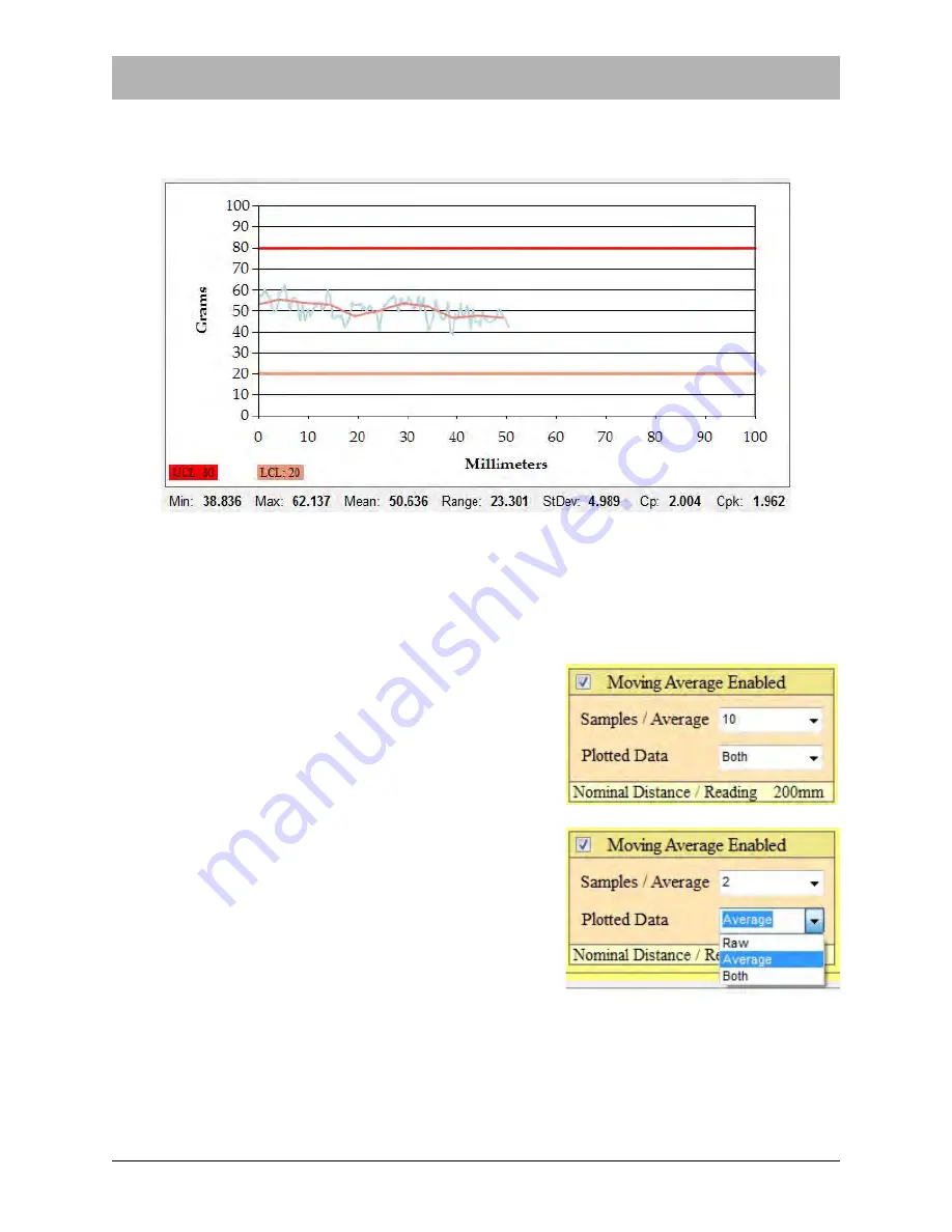
, the PT-55 will calculate a moving average based on a preset

number of sample readings. The 

Pull Test Graph 

in the 

Main Screen 

can now


display a graph

with either the raw individual readings (

blue

) or the Moving Average (

pink

) or both. 

When the 

Moving Average

 is between the upper and lower control limits, the test result will be

PASS

. If the 

Moving Average

 exceeds those limits, the test result will be 

FAIL

.

Note: 

If the 

Moving Average

 is between the preset upper and lower limits but the individual

readings exceed those limits, the test result will still be 

PASS

.

When Moving Average is enabled, the user must select
the number of 

Samples/Average

. This can be set from

2-10

The 

Plotted Data

 field allows the user to choose what

data appears in the 

Main Screen

 graph when a test is

run. The options are 

Raw

 (individual test readings),

Average

 and 

Both

.

Summary of Contents for PT-55

Page 1: ...PT 55 SMD Tape Peel Force Tester User s Guide V TEK Inc 751 Summit Avenue Mankato MN 56001 P 507 387 2039 www vtekusa com User s Guide D291308 AG...

Page 2: ......

Page 3: ...f machinery Safety Related Parts of Control Systems Part 1 General Principals for Design EN ISO 13732 1 2008 Safety of machinery Ergonomics of the thermal environment Methods for the assessment of hum...

Page 4: ......

Page 5: ...ibes how to setup and operate the PT 55 SMD Peel Force Tester It should be read and thoroughly understood before operating the machine Theory of Operation Operation of the PT 55 is simple The operator...

Page 6: ...range of 0 degrees Celsius to 60 degrees Celsius such temperature may decrease the life of some of the components The recommended rating is 0 degrees Celsius to 50 degrees Celsius Humidity 5 to 90 non...

Page 7: ...ing of 200 to 300 Lux Lumens m2 The recommended climate is between 5 90 non condensing humidity with a room tempera ture between 0 50 degrees Celsius Note Although all of the components used on the ma...

Page 8: ...ucate the user about how to operate the PT 55 safely They contain important information on avoiding potential hazards to the operator and to the equipment Safety Precautions Observe the following safe...

Page 9: ...embly Details 5 Serial Plate 6 Chapter 2 Setup 7 Preparing the Work Area 8 Laptop Security Bracket Installation 10 Software Setup 13 Auto Tension Setup 18 Save Mode Setup 21 Peel Force Test Setup 22 C...

Page 10: ...Export File 61 Creating an maf Export File 63 Customizing the Main Screen Logo 65 Chapter 4 Maintenance Calibration 67 Recommended Maintenance 68 Calibration 69 Verify Calibration Accuracy 73 Appendix...

Page 11: ...Chapter 1 Machine Overview Contents Machine Overview 2 Rear Panel 3 Load Cell Details 4 Carriage Assembly Details 5 Serial Plate 6...

Page 12: ...as the two separate is transferred from the alligator clip through the chain to the load cell C Carriage Assembly The carrier tape is attached to the motorized carriage assembly when taking a peel for...

Page 13: ...Rear Panel A Power Switch ON OFF switch for the PT 55 B AC Receptacle AC power supply plug C Optional Security Bracket Security bracket used for securing the laptop to the PT 55 D USB Port Connector...

Page 14: ...4 PT 55 User s Guide Load Cell Details D291308 4f fm Load Cell Details A Load Cell Position Screw B Load Cell C Alligator Clip Figure 1 4 A C B...

Page 15: ...y Details Chapter 1 Getting Started 5 Carriage Assembly Details A Idler Wheel B Calibration Jig C Carriage Front Track Guide D Sprocket Wheel E Track Adjustment Knob F Carriage Clamp remove before ope...

Page 16: ...fm Serial Plate The PT 55 Serial plate contains critical machine information including Electrical details docu mentation and ratings model manufacture date and serial number and contact information f...

Page 17: ...Chapter 2 Setup Contents Preparing the Work Area 8 Laptop Security Bracket Installation 10 Software Setup 13 Auto Tension Setup 18 Save Mode Setup 21 Peel Force Test Setup 22...

Page 18: ...4 wide by 15 deep to provide sufficient space for the assembled machine Ideally the table height should be adjustable so the machine height can be easily adjusted to suit operators of varying heights...

Page 19: ...llow at least 24 clearance at the front and sides of the machine for easy access and operation Pictured in the overhead view below The PT 55 will also require access to a 120 230 VAC 50 60 Hz power su...

Page 20: ...work on a PC running Windows XP Home SP3 Windows XP Pro SP3 or Windows 7 Note If the computer has issues starting up when the USB ports are in use see the Appen dix at the end of this manual for BIOS...

Page 21: ...D291308 5q fm Laptop Security Bracket Installation Chapter 2 Setup 11 2 Remove the thumb screw on the left side of the machine 3 Lift off the top of the PT 55 Figure 2 2 Figure 2 3...

Page 22: ...et Installation D291308 5q fm 4 Set the security bracket on top of the PT 55 Put the two 5 16 18 BHCS through the holes of the PT 55 and security bracket 5 Tighten the two 5 16 18 nuts on the bolts 6...

Page 23: ...for this laptop Creating a recovery disk is solely the users responsibility PT 55 Interface Software Instructions 1 Insert flash drive into PC that will host the interface software 2 Double click on t...

Page 24: ...291308 5q fm 6 The Ready to Install Program screen will open Click Install 7 The Install Shield Wizard Completed screen will open Click Finish to complete installation 8 The PT 55 Icon will now appear...

Page 25: ...l run the PT 55 1 Turn the PT 55 ON then connect the computer to the PT 55 with the USB Cable 2 Open the Start Menu on the target system by clicking the icon on the right Right click Computer and sele...

Page 26: ...ivers and unzip the driver files Select x64 for 64 Bit OS Select x86 for 32 Bit OS 5 Within the System Control Panel click Device Manager 6 As shown below find the unknown device in the Device Manager...

Page 27: ...ct Browse My Computer for Driver Software and browse to c V Tek PT 55 Drivers x64 Note x64 is based on a 64 bit OS as previously described For 32 bit systems this location needs to be x86 8 Click Next...

Page 28: ...elected and a value is entered the peel force graph will wait until the auto tension value is reached After this it will reset the graph and will start plotting the peel force test Setting the Auto Te...

Page 29: ...Options section ensure Auto Ten sion is Enabled Enter the Tension Threshold value and the Tension Delay value in milliseconds The delay is the time from which the carriage assembly starts moving and w...

Page 30: ...ion Setup D291308 5q fm 6 The Tensioning message will flash over the graph until the Auto Tension Value is exceeded 7 The PT 55 will then automatically reset the graph and begin plotting the peel forc...

Page 31: ...specific file name and location once the test is completed In Auto Sales Order mode the file is saved to a specific location under the sales order number Setting the Save Mode 1 Select the Supervisor...

Page 32: ...about 6 to 12 inches long Make sure the entire length of the strip has been sealed under the same conditions Cut the strip free from the taping machine and bring it to the peel force tester 2 Orient t...

Page 33: ...sprocket by placing the sprocket holes over the pins Lower the idler wheels so the tape is captured on the tape sprocket 6 Pull the load cell assembly out to a position where the chain is centered on...

Page 34: ...the preset Pull Length You may also press the Stop Test button when enough data has been gathered to complete the test The Main Screen will then display a PASS or FAIL message The photo above shows a...

Page 35: ...30 Auto Manual Connect 34 Peel Test Statistics 35 Supervisor Settings Screen 39 Customize Main Screen Fields 40 Supervisor Settings 46 GRAPH OPTIONS 46 SYSTEM OPTIONS 48 SAVING OPTIONS 48 ADVANCED OPT...

Page 36: ...ware package This program will operate the carrier tape drive assembly and generate a graphic dis play of the peel force required to remove the cover tape It is possible to record the peel test result...

Page 37: ...arameters perform tests and observe test results All of the fields will be blank Menus The File Menu is located in the top left corner of the Main Screen File Menu Selecting Open will allow the operat...

Page 38: ...be kept for records Print setup allows the user to select a printer and configure print settings The Exit command will close the PT 55 Software program Any unsaved data will be lost Customer Machine...

Page 39: ...t Note With the exception of Pull Length the Settings fields may only be changed by using a supervisor pass word Pull Length Setting the pull length allows the user to stop the peel force at a desired...

Page 40: ...e Settings section The example below shows a Peel Test Graph after settings have been configured and before the test has been run The Upper Limit value of 90 is represented by a red line while the Low...

Page 41: ...uto tensioning is in progress Once Auto Tensioning is complete the PT 55 will automatically begin the pull test During and after a peel test the Peel Test Graph displays the test results The test belo...

Page 42: ...e moving average All readings are between the Upper and Lower Limit values a PASS result The test below shows Moving Average Enabled in the Supervisor Screen The blue line repre sents all readings The...

Page 43: ...33 The test below shows Moving Average Enabled in the Supervisor Screen The blue line repre sents all readings The pink line represents the moving average Both the readings and the mov ing average ex...

Page 44: ...s ONLINE The PT 55 s Autoconnect feature looks for a disconnected state every 15 seconds and automat ically reconnects the PC to the PT 55 if it senses the computer is OFFLINE While the HMI is reconne...

Page 45: ...ted from the maximum peel force test StDev Sample Standard Deviation Measurement of how much the data is scattered The formula for this calculation is Cp Process Capability An indicator of process cap...

Page 46: ...cess and dis plays a Pass or Fail message in the Main Screen Note Seal Tests stop automatically when the test reaches its Pull Length setting Clicking Stop Test allows the operator to stop the test as...

Page 47: ...any previously saved jobs Note Files are automatically saved to a Recipe rcp for mat However if earlier versions of PT 55 software were used to save files they will appear as Legacy txt files Reset Cl...

Page 48: ...en printing Select the printer and then click on OK An exact copy of the screen including the test and customer data will be printed The printout can then be kept for records Home Press Home to reset...

Page 49: ...pt and click OK Note The default password is password Click the Change Password button in the Supervisor Settings screen to create a new password After the correct password is entered the Supervisor S...

Page 50: ...n the check box next to the field you d like to edit to open the Change Data window The Change Data window allows the user to customize each field s Label Visibility and Input Type Editing Field Label...

Page 51: ...now appear as follows Editing Field Visibility The Supervisor Settings screen can also be used to change the visibility of a field This is useful for streamlining test data entry for operators as unu...

Page 52: ...ected the field no longer appears in the Main Screen In the example above the Sales Order field which used to appear above the Part Number field is no longer visible Editing Field Input Choices There...

Page 53: ...information When the Pressure or Temperature fields are selected an Operator entered double option appears under Input Type This creates two text entry fields to allow the operator to track Inside an...

Page 54: ...of the screen then press the Enter key The text will now appear in the Input Choices section To change the Input Choice select the current choice and click Remove Then enter the desired data in the N...

Page 55: ...selection drop box for the field To create a drop down option enter the desired text in the New Choice field at the bottom of the screen then press the Enter key The new option will now appear in the...

Page 56: ...ill display There are three setting options for travel distance 100 mm 150 mm and 200 mm Note If a Pull Length value of 0 is entered in the Main Screen Settings field the pull length will be the maxim...

Page 57: ...per and lower control limits the test result will be PASS If the Moving Average exceeds those limits the test result will be FAIL Note If the Moving Average is between the preset upper and lower limit...

Page 58: ...rce graph will wait until the auto tension value is reached After this it will reset the graph and will start plotting the peel force test The Auto Tension Checkbox default setting is ON checked The A...

Page 59: ...s auto saved at 4 40 30 PM on October 22 2014 the File Name will be My File_2014 10 22_16 40 30 Similarly if Auto Sales Order Mode is selected and the file for Sales Order 1234567 is saved at the same...

Page 60: ...lowing a test Note the Mean Reading now appears beneath the Supervisor button SUPERVISOR BUTTONS Pressing the Change Password button will open the Change Password Screen Pressing the Calibrate button...

Page 61: ...rvisor Settings Screen Chapter 3 Operation 51 Pressing the Validate button will place the PT 55 in Validation Mode which verifies calibration accuracy See Chapter 4 for a detailed description of the v...

Page 62: ...s Guide Supervisor Settings Screen D291308 7M fm Save Supervisor Settings Once the Supervisor Settings screen is configured as desired click Save Exit to save the settings and return to the Main Scree...

Page 63: ...a Peel Test Note For information on machine setup and loading tape see Chapter 2 Setup For information on configuring the Main Screen fields see the previous sections in this chap ter 1 Start the appl...

Page 64: ...for Name Part Number Reel Number Name Shift and the Temperature Pressure and Dwell Time used to create the seal being tested 3 Enter carrier tape information in the Carrier fields for Supplier Type an...

Page 65: ...rvisor button to access the Password Input screen and open Supervisor Settings The Password Input screen will appear Enter the password at the prompt and click OK Note The default password is password...

Page 66: ...to the X Axis Maximum which was set in the Supervisor Settings screen If the X Axis Maximum setting is different than the Pull Length setting the pull test will stop at whichever length is shortest 8...

Page 67: ...on 57 10 Click the Start Test button to begin the peel force test Test results will be displayed on the Peel Force Test Graph and in the fields below the graph 11 Click Stop Test to end the test at an...

Page 68: ...pear at the bottom of the Main Screen 13 After the pull test is complete it may be saved or printed using the buttons on the bottom cor ner of the Main Screen Other options include resetting the test...

Page 69: ...o that the parameters do not have to be re entered each time they are used Multiple forms can be created and stored if desired Creating a Master Form 1 Start the PT 55 software by double clicking the...

Page 70: ...7M fm 4 The Save screen will open 5 Enter a file name and press SAVE 6 To retrieve the master form later click Open File and select the desired file A new test can now be run using the previously ent...

Page 71: ...v format This file is an Excel compatible data file which may be used to create a spreadsheet which can then be customized as desired The following information is stored in each record Customer Machin...

Page 72: ...will be saved to a Comma Separated Value csv format This document can be opened in a text file reader such as WordPad or imported into an Excel Spreadsheet A sample csv text file is pictured below Not...

Page 73: ...file is an Excel com patible data file which may be used to create a spreadsheet which can then be customized as desired The following information is stored in each record Customer Machine data Carrie...

Page 74: ...will be saved to a Moving Average File maf format This docu ment can be opened in a text file reader such as WordPad or imported into an Excel Spread sheet A sample maf text file is pictured below Not...

Page 75: ...insert a different logo into the field currently occupied by the V TEK logo on the Main Screen follow the steps below 1 Find an appropriate bitmap logo file 2 Rename the logo comlogo bmp 3 Save the ne...

Page 76: ...66 PT 55 User s Guide Customizing the Main Screen Logo D291308 7M fm...

Page 77: ...Chapter 4 Maintenance Calibration Contents Recommended Maintenance 68 Calibration 69 Verify Calibration Accuracy 73...

Page 78: ...grams of the full scale value of the load cell The load cell range is 0 200 grams It must be noted that a number of factors can affect the accuracy of the system and cause the readings to differ from...

Page 79: ...ts sold separately Calibration Procedure In the event that the load cell is replaced or if it is part of a maintenance routine the load cell can be recalibrated by following the steps outlined Note On...

Page 80: ...er the password at the prompt then click OK Note The default password is password 3 The Supervisor Settings screen will open 4 Click Calibrate The following message will appear Click OK The carriage w...

Page 81: ...rst is to remove any objects from the load cell clip 6 Once the load cell clip is empty place the clip on top of the load cell to remove any downward force on the load cell Click OK 7 The next step is...

Page 82: ...ge assembly before con necting them to the load cell clip Never hang weights without using the calibration jig Hang ing weights directly from the load cell may cause damage to the load cell 8 Repeat S...

Page 83: ...curacy Chapter 4 Maintenance Calibration 73 Verify Calibration Accuracy 1 Click Validate to verify the calibration 2 The following message will appear 3 Click OK then click Save Exit to return to the...

Page 84: ...changed to a Validate button 5 Ensure the carriage is in the home position then hang a 50g or 100g weight from the load cell suspending it over the calibration jig just as it was during the calibratio...

Page 85: ...ngs to the right of the graph and below it 7 Let the chart record at least 50mm of travel then press Stop Test 8 The Mean value is displayed under the graph It should be 3g from the nominal value of t...

Page 86: ...76 PT 55 User s Guide Verify Calibration Accuracy D291308 6r fm Once validation is complete the dialog screen on the right will appear Select No to exit Validation Mode...

Page 87: ...D291566 1 fm Appendix A Changing the Computer BIOS Setting A 1 Appendix A Changing the Computer BIOS Setting...

Page 88: ...er running BIOS version 1 46 6JET88WW Screens and instructions may vary slightly when working with other computers although the required boot priority order will remain the same 1 Power the computer o...

Page 89: ...Press F6 three times to move ATA HDD0 to the top position on the list as shown below 7 Press F10 to save this setting and exit Boot Options 8 The Setup Confirmation dialog will open With Yes highligh...

Page 90: ......

Page 91: ...on 15 17 E export file 49 61 64 F features i field visibility 41 input choices 42 44 45 G graph 30 33 46 47 I input type 40 45 inserting company logo 65 install security bracket 10 12 intended use iii...

Page 92: ...49 save file 36 settings 48 49 52 security bracket optional 3 8 10 12 serial plate 6 settings fields 17 28 29 40 45 setup laptop security bracket 8 10 12 software 13 14 auto tension 18 20 31 48 save m...

Page 93: ...control board 1 157004 Motor stepper 1 157005 Motor stepper driver 1 157008 Panel light 1 157012 USB cable 3FT male A to MA 1 204012 Drive bearing 2 204054 Bearing 2 204056 Bearing 1 8Dx3 8OD flanged...

Page 94: ...PT 55 Spare Parts List D291427h fm Page 1 of 1...

Page 95: ...E S U R O D E T T I M S N A R T D E C U D O R P E R E B T O N Y A M N M O T A K N A M C N I K E T V F O N O I S S I M R E P 4 9 2 1 9 2 G D E I F I C E P S E S I W R E H T O S S E L N U 2 3 X X X 5 0...

Page 96: ...E H T T U O H T I W D E S U R O D E T T I M S N A R T D E C U D O R P E R E B T O N Y A M N M O T A K N A M C N I K E T V F O N O I S S I M R E P 4 9 2 1 9 2 G D E I F I C E P S E S I W R E H T O S S...

Page 97: ...O F N I E H T S S E R P X E E H T T U O H T I W D E S U R O D E T T I M S N A R T D E C U D O R P E R E B T O N Y A M N M O T A K N A M C N I K E T V F O N O I S S I M R E P 4 9 2 1 9 2 G D E I F I C...

Page 98: ...A M R O F N I E H T S S E R P X E E H T T U O H T I W D E S U R O D E T T I M S N A R T D E C U D O R P E R E B T O N Y A M N M O T A K N A M C N I K E T V F O N O I S S I M R E P 4 9 2 1 9 2 G D E I...

Page 99: ...4 2 0 1 1 7 6 4 7 9 8 5 2 T E K C O R P S E V I R D 1 8 6 1 1 1 2 6 2 N O I T A C I F I D O M R A E G R U P S 1 9 6 5 9 7 2 6 2 0 0 5 B O N K T N E M T S U J D A 1 4 7 7 1 7 5 6 2 F F O D N A T S K C...

Page 100: ...I N O I T A M R O F N I E H T S S E R P X E E H T T U O H T I W D E S U R O D E T T I M S N A R T D E C U D O R P E R E B T O N Y A M N M O T A K N A M C N I K E T V F O N O I S S I M R E P 4 9 2 1 9...

Page 101: ...L F S S 3 M 2 2 6 1 0 0 9 3 2 T U N X E H S S 0 4 4 2 9 7 9 2 7 5 6 2 T N U O M H C T I W S T I M I L 2 T I L A I T N E D I F N O C D N A Y R A T E I R P O R P S I T N E M U C O D S I H T N I N O I T...

Page 102: ...A M N M O T A K N A M C N I K E T V F O N O I S S I M R E P 4 9 2 1 9 2 G D E I F I C E P S E S I W R E H T O S S E L N U 3 6 X X X 5 0 0 0 X X 0 1 0 0 X 5 1 0 0 D E N I H C A M 1 0 D N E B 5 0 N W A...

Page 103: ...0 X 5 1 0 0 D E N I H C A M 1 0 D N E B 5 0 N W A R D R P P A G N E E T A D E M A N L L E C D A O L H R 3 1 1 0 1 D C B A A B C D 1 2 3 4 5 6 7 8 8 7 6 5 4 3 2 1 E L T I T E Z I S O N G W D V E R s b...

Page 104: ...E T T I M S N A R T D E C U D O R P E R E B T O N Y A M N M O T A K N A M C N I K E T V F O N O I S S I M R E P 9 4 2 1 9 2 C D E I F I C E P S E S I W R E H T O S S E L N U 3 6 X X X 5 0 0 0 X X 0 1...

Page 105: ...____________________________________________________________ ____________________________________________________________ ____________________________________________________________ ________________...

Page 106: ...Service and Parts Contacts 61053915 fm Page 2...

Page 107: ...2 Setup Pages 7 24 D291308 5q fm Chapter 3 Operation Pages 25 66 D291308 7m fm Chapter 4 Maintenance Pages 67 76 D291308 6r fm Appendix A Changing the BIOS Page 1 of 2 D291566 1 fm Index Page 1 of 2 D...

Page 108: ......

Page 109: ...not assume any liability for damage incurred during shipment 8 For the first 30 days that you own your V TEK product V TEK will be responsible for ground shipments to and from V TEK s facility in Mank...

Page 110: ......

Page 111: ......

Page 112: ...751 Summit Avenue Mankato MN 56001 507 387 2039 FAX 507 387 2257 www vtekusa com Email info vtekusa com...

Reviews: