background image

Section 1

1-17

Components

Section  1

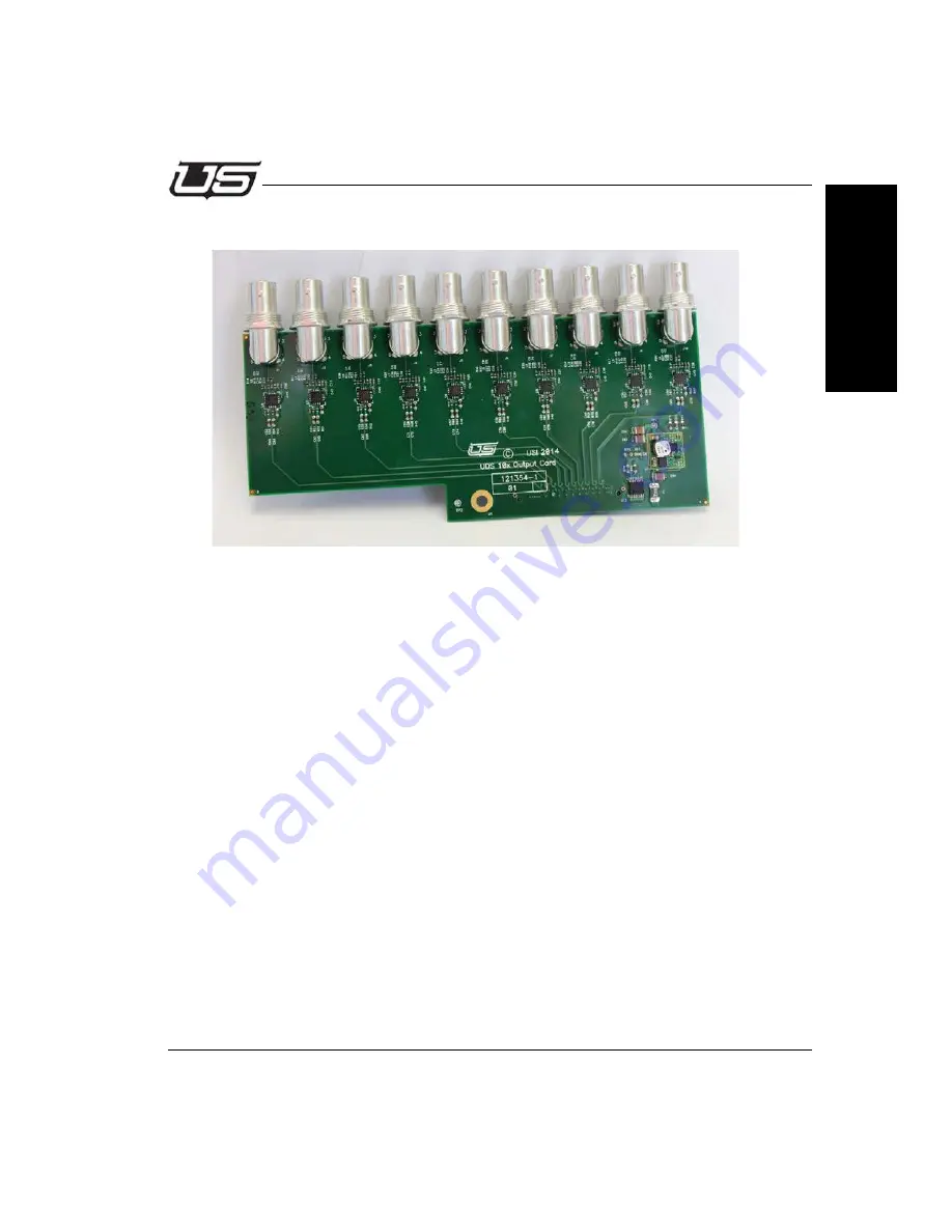
Expansion Output Card (121354-1) Revision 02

Figure 1-16.

121354-1 Here

This card is a simple board that receives 10 output signals from the crosspoint core and 
drives them out of BNC’s. It has a local power supply and control circuitry.

Power Supplies

The 12 VDC from the base card is fused and then regulated to 3.3 VDC by U11. This page 
also details a small I2C IO expander (U12) that identifies this card as an output card.

Output Circuits

Outputs 1-10 are made up of signals delivered to this board from the crosspoint, and then 
driven out of BNC’s by M21328 cable drivers.

Summary of Contents for UTAH-100/UDS 10x10

Page 1: ...UTAH 100 UDS Compact Router Series System Setup and Operation ...

Page 2: ...ange without notice or obligation While every effort has been made to ensure that the information is accurate as of the publication date Utah Scientific Inc assumes no liability for errors or omissions In addition Utah Scientific Inc assumes no responsibility for damages resulting from the use of this guide FCC Compliance USA and Digital Equipment Com pliance Canada This equipment has been tested ...

Page 3: ...uipment in a residential area is likely to cause harmful interference in which case the user will be required to correct the interference at their own expense Shielded cables must be used to ensure compliance with the FCC Class A limits ...

Page 4: ...nce with the following standards Emission EN55022 1994 A1 A2 Immunity EN55024 1998 EN61000 3 2 EN61000 3 3 Safety IEC 60950 1 2001 EN 60950 1 2001 Following the provisions of the Directive s of the Council of the European Union EMC Directive 89 336 EED Low Voltage Electrical Directive 72 23 EEC Utah Scientific Inc hereby declares that the product specified above conforms to the above Directive s a...

Page 5: ...ing the chas sis changing a power supply or removing a board should be performed by qualified personnel only To reduce the risk of electric shock do not perform any service unless you are qualified to do so Heed all warnings on the unit and in the operating instruc tions Do not use this product in or near water Disconnect AC power before installing any options or servicing the unit unless instruct...

Page 6: ...ment as they may open abruptly and injure you To avoid fire hazard when replacing fuses use only the specified correct type voltage and current rating as ref erenced in the appropriate parts list for this product Always refer fuse replacement to qualified service per sonnel Have qualified personnel perform safety checks after any service Cautions Please observe the following important cautions Whe...

Page 7: ...ephone 1 801 575 8801 FAX 1 801 537 3098 Technical Services voice 1 800 447 7204 Technical Services FAX 1 801 537 3069 E Mail General Information info utsci com E Mail Technical Services service utsci com World Wide Web http www utahscientific com After Hours Emergency 1 800 447 7204 Follow the menu instructions for Emergency Service ...

Page 8: ...mer Remedies For the first one 1 year after purchase of the software and the first two 2 five 5 or ten 10 years after the date of purchase of the hardware Utah Scientific s and its suppliers entire liability and purchaser s exclusive remedy shall be at Utah Scientific s option either Return of the price paid or Repair or replacement of the software or hardware that does not meet the above warranti...

Page 9: ...tes jurisdictions No liability for consequential damages To the maximum extent permitted by applicable law in no event shall Utah Scientific or its suppliers be liable for any damages whatsoever including without limitation damages for loss of business profits business interruption loss of business information or any other pecuniary loss arising out of the use of or inability to use Utah Scientifi...

Page 10: ...x ...

Page 11: ... Connections 1 10 Video Connections 1 11 Front Panel Controls and Indicators 1 12 Power LED 1 12 Reset Switch 1 12 Components 1 13 Base Crosspoint Card 121352 1 Revision 02 1 13 Power Supplies 1 13 Control Circuitry 1 14 Crosspoint 1 15 Input Circuits 1 15 Output Circuits 1 15 Bi Directional Circuits 1 15 Expansion Connectors 1 15 Expansion Input Card 121353 1 Revision 02 1 16 Power Supplies 1 16 ...

Page 12: ...tivation and Configuration 2 9 Panel Applet Activation and Configuration 2 12 Section 3 The Router Applet Router Configuration 3 1 Security 3 3 Data Comm 3 4 TCP RCP 3 Network 3 4 Serial RCP 1 3 4 DHCP 3 5 Sources 3 6 Destination Creation from Within the List 3 12 Panel Views 3 14 Sorting Option 3 15 Destination Blocks 3 18 Salvos 3 19 Accounts 3 22 Save Button 3 24 Router Control 3 25 Source and ...

Page 13: ...nfiguration 4 3 System 4 5 Network 4 5 Network Parameters 4 6 Encoding 4 6 Panel Layout Config Controls 4 7 Layouts Single and Multi Dest 4 9 Single Destination 4 9 Multi Dest layout 4 10 XY 32 Configuration 4 11 Print Option 4 14 Control Panel 4 15 Section 5 Specifications and Alarms Frame Specifications 5 1 Width 5 1 Depth 5 1 Sizes 5 1 Power Supply 5 1 Control Connections RJ 45 Ethernet 5 2 I O...

Page 14: ...Take Report Enable A 3 Matrix Take Report Disable A 3 Matrix Section Refresh A 3 Matrix Take Command A 4 CALCULATE Checksum A 5 MISC items A 5 Appendix B System Update Introduction A 1 System Setup Requirements A 2 Settings File Update A 2 Updating the Router Config Applet A 3 Updating the Panel Config Applet A 6 Appendix C Troubleshooting Hard Reset B 1 Factory Reset B 1 Serial Port Network Confi...

Page 15: ...able of Contents v Table of Contents Appendix D Maintenance Functions In This Appendix D 1 Changing Button Legends D 2 Using the Template D 3 Removing and Inserting button legends D 5 Ordering Parts D 6 ...

Page 16: ...vi UTAH 100 UDS Setup Operations Guide ...

Page 17: ...ing of automation systems hardware based control panels or software based control panels RS 232 or RS 422 control is also available using standard RCP 1 protocols to a single DB9F port on the chassis The 10x10 and 20x20 routers can be ordered with or without an integral control panel on the front of the unit This control panel provides dedicated output and input select buttons that are fixed funct...

Page 18: ... Sec and 2 970 Gb Sec and any other frequency is passed with the reclocking automatically bypassing The reclocking feature is DVB ASI compatible Very long cable lengths are achieved by reclocking each input signal directly after it is received providing the cleanest signal possible to the system Figure 1 1 UT 100 UDS 10x10 20x20 and 8x32 ...

Page 19: ...ion slots are filled with Output Expansion Cards and the system automatically makes the bidirectional ports Outputs when this configuration is recognized resulting in an 8x32 port system Each system can contain a local control panel The default configurations have the 8x32 without a local panel the 10x10 with a local 20 button panel and the 20x20 with a local 40 button panel These local panels hav...

Page 20: ...1 4 System Setup Overview System Diagrams UDS 10x10 UDS 20x20 ...

Page 21: ...Section 1 1 5 Introduction Section 1 8x32 DA UDS XY ...

Page 22: ...nnections power connectors Figure 1 4 140033 08 power supply here There are two captive nut power connections on the rear of the chassis They accept input from the 140033 08 Utah Scientific 30W power supply Either port can be used and one or two supplies can be connected or redundancy ...

Page 23: ...port so if desired it can be connected directly to a PC or UDS Remote Control Panel without the need for a crossover cable Cable lengths of up to 100 meters are supported This port is 10 100 capable The two LED s in this port indicate link state and speed Both LED s ON solidly indicate no link The LH LED flashing and the RH LED solid indicate 10 Mb Sec link The LH LED flashing and the RH LED off i...

Page 24: ...rd RCP 1 protocols Contact Utah Scientific Customer Support for a copy of this protocol The baud rate data start stop bit configuration and 232 422 mode of this port are configured in the Web Based GUI described in Section 2 of this manual The pinout of this port is Table 1 7 DB9 Pin RS 232 Signal RS 422 Signal 2 TX TX 3 RX RX 5 Ground Ground 7 N C TX 8 N C RX ...

Page 25: ...Personnel may ask you to connect a serial port here to diagnose certain issues The system is delivered with an adapter USI PN 140033 15 that allows you to connect a CAT5 patch cord to this port then to the adapter and then to an RS 232 port on a standard PC The pinout of this port is Table 1 9 RJ45 Pin RS 232 Signal 1 UDS Debug TX 2 Ground 4 SC CPU Debug TX 5 SC CPU Debug RX 7 Ground 8 UDS Debug R...

Page 26: ...re 1 11 Rear Panel Center BNC on the lower row The BNC on the lower row of the router directly in the center is for an analog reference signal used to switch the router in vertical interval Connect Analog Black Burst or Tri Level Sync to this port DB9S to RJ45 Name PIN Wire Color PIN GND 5 Brown 7 RX 2 White 1 TX 3 Blue 8 ...

Page 27: ...2 Rear Panel label indicating IO Numbers The 40 BNC connectors have different numbering based on the 3 different configurations Each configuration has a label indicating which BNC s are which Refer to this label when connecting Input or Output Coax cables to the BNC s ...

Page 28: ... switch momentarily will reset all processing functions Holding this switch in for 10 seconds will default all configuration settings to the original factory settings The IP setting s default is 192 168 5 180 The serial port default is RS 232 115k baud 8 N 1 RESET LINK IN IN IN IN IN IN IN IN IN IN IN IN IN IN IN IN IN IN IN IN 1 2 3 4 5 6 7 8 9 10 11 12 13 14 15 16 17 18 19 20 Power LED Reset Swi...

Page 29: ... two external power supplies The 12VDC rail feeds the two attached fans directly and also feeds the three regulators that create the lower DC voltages required for the board U35 creates a 6 amp 3 3V rail U29 creates a 2 amp 2 5V rail and U24 creates 6 amp 1 2V rail All of these supplies are fixed output and non adjustable U34 an LTC2910 voltage supervisor monitors all of the voltage and generates ...

Page 30: ...H V and F to the FPGA The front panel switches and LED s are monitored and controlled by a soft core processor inside the FPGA A general description of the control lines from the FPGA are FPCA1 8 These lines make up two I2C busses reset and presence control lines for the front panel SG1 6 Control lines to the Scangate device Page 8 that allow the CPU to read the board part number and revision ECON...

Page 31: ...the crosspoints Output Circuits There are 10 dedicated outputs on the board They are DC coupled to the crosspoint and the outputs driven by M21328 cable drivers Bi Directional Circuits Two LMH0387 bi directional components make up the bi directional ports They function as cable equalizers or cable drivers depending on the state of the RX pin There is both an input and an output connection to the c...

Page 32: ...1 2 VDC 2 amp rails by U17 U15 and U14 respectively This page also details a small I2C IO expander U18 that identifies this card as an input card Input Circuits Inputs 1 10 are made up of M21564 cable equalizers that feed M21350 reclocking components These reclocker s automatically lock to and reclock signals at 270 1485 and 2970 Mb Sec rates and automatically bypass other signals The bandwidth is...

Page 33: ...them out of BNC s It has a local power supply and control circuitry Power Supplies The 12 VDC from the base card is fused and then regulated to 3 3 VDC by U11 This page also details a small I2C IO expander U12 that identifies this card as an output card Output Circuits Outputs 1 10 are made up of signals delivered to this board from the crosspoint and then driven out of BNC s by M21328 cable drive...

Page 34: ... keys are polled and the top row of LED s lit by one I2C bus and the lower row of keys lit by another I2C bus This allow short loading of the maximum number of components for the 10x10 panel The Left Hand 20 buttons are outputs and the right hand 20 buttons are inputs System Interface J1 is a 20 pin connector that carries 3 3 VDC from the base card as well as reset signals I2C Busses and key press...

Page 35: ...parate output of the TCA6416 I2C IO expander associated with that bank of LED s 10 per Output Switches and LED s The Output section has a green and a red LED for each switch to provide an amber backlit color The same voltage divider and transistor for actively lighting the LED s is use in this section Button Legends The legends in this panel can be remade to label them for a users facility See App...

Page 36: ...1 20 System Setup Overview ...

Page 37: ...uration Introduction This guide describes the network configuration for the UTAH 100 UDS Router and Panel Using two setup scenarios New Configuration on an Independent Network and New Configuration on an Existing Network These are the first steps required to configure and control the system ...

Page 38: ...7 07 or newer Internet Explorer Firefox or Chrome Ethernet connection All UDS devices PC Router and Panel connect over Ethernet on a house network or within a stand alone direct mode The system will provide default IP address during setup or you can use unique IP addresses if required within your operation ...

Page 39: ...relatively simple involving Ethernet connection between the PC and devices router and panel only as a stand alone network Simply connect all devices together as shown in Figure 1 for basic setup In this case you will only need to set the PC address to the same subnet as the router and panel This will facilitate applet operation and table configuration The following default IP addresses below ship ...

Page 40: ...s router and panel must occupy the same subnet 1 See your network administrator for configuration assistance if no default subnet appears Online instruction is also available by accessing the HTML help file located within the applets which will also provide details for setup and configuration of the router and panel tables 1 All routers and panels require separate IP addresses ...

Page 41: ...figuration on an existing network Use this routine if you need to modify the router or panel s network parameters The steps below are based on the default set of parameters On the PC click Control Panel Network and Internet Network Sharing Center then Change Adapter Settings 1 FIGURE 2 1 These steps are based on Windows 7 operation ...

Page 42: ...6 Network Configuration Network Configuration When the following window appears right click the icon to produce the drop down menu then select Properties FIGURE 3 The following window will appear FIGURE 4 ...

Page 43: ...100 UDS Network Configuration Section 2 Select Internet Protocol Version 4 then click the Properties button The following win dow will appear FIGURE 5 Click the second radio button down to set a static IP address FIGURE 6 ...

Page 44: ...to the router with a standard Ethernet cable Note A crossover cable typically used with an Ethernet connection is not necessary as the signal switch is done internally 1 This is the subnet default address You can substitute the last digit if required for your system If your system contains a completely different subnet for the PC routers and panels substitute the correct addresses where applicable...

Page 45: ...the applet does not activate try pinging the system by opening your command prompt and typing the router s IP address address number ending in 180 to determine whether or not the connection is good If you are unable to ping the device check the connec tions or see the network administrator for additional help In addition if you are unsure of the IP address you may need to default the router to the...

Page 46: ...ns appears select Router Configuration FIGURE 9 Note You will only be able to connect if the browser window shown in Figure 9 indicates Applet ready for login d Enter Username admin default in the username entry box e Enter Password admin default in the password entry box ...

Page 47: ...ss in the space provided h Verify the Port setting of 5001 i Make sure the DHCP box is unchecked j Click the Program Router button when the network configuration is complete k A dialog will appear prompting you to reset the device To make the IP changes active reset the router by pressing and quickly releasing the small button at the far right side of the control module on the back of the router N...

Page 48: ...y bringing up a web browser and entering 192 168 5 181 factory default setting in the URL browser box Click the Panel Configuration icon to log in as shown in the figure below FIGURE 11 In this mode the Panel Applet dialog will indicate the router s absence 1 The following dialog will appear with no router connected FIGURE 12 1 This is a simple operational scenario with no router currently connect...

Page 49: ...sses are in place then reset the system A dialog will appear prompting you to reset the device To make the IP changes active cycle the power to the panel or reset the panel by pressing and quickly releasing the small button at the far right side of the control module rear of panel Once the above steps are complete the panel can be placed on the target network and configured as needed You can now l...

Page 50: ...2 14 Network Configuration Network Configuration ...

Page 51: ...UDS Browser Utility The Router Applet Router Configuration Router Configuration is activated by launching the browser applet using the supplied default IP address This section contains the steps involved in activation and operation of the UTAH 100 UDS Router Applet ...

Page 52: ...ter to communicate properly Once the necessary hardware is in place start the application with the provided IP address then launch the applet by clicking the Router Configuration icon Figure 3 1 You will be prompted to log in with your username and password The default is admin admin Figure 3 2 ...

Page 53: ...sociated accounts are loaded into the system at the time of the initial launch Current User Figure 3 3 Security The default user is listed in the Current User cell You can change users from the list of previously designated users Switch User button Users are selected from this dialog but not configured Figure 3 4 ...

Page 54: ... location along with the RCP 3 port setting Alternatively you can select DHCP to automatically set network parameters The only way to verify the IP address setting in DHCP mode is to access the DHCP server Figure 3 5 Serial RCP 1 This area allows for enabling or disabling RCP 1 checkbox and assigning the parameters associated with serial format baud rate data bits parity and stop bits Figure 3 6 ...

Page 55: ...DHCP box to activate the connection The address cells will gray out when the box is clicked The only way to verify the IP address setting in this mode is to monitor the DHCP server via serial connection Once network modifications are complete IP changes click the Program Router button Figure 3 7 The configuration successful dialog will appear Figure 3 8 ...

Page 56: ...ed Since this is not the likely desired configuration highlight the unwanted sources and click the Remove button Figure 3 9 Source Creation New Sources are defined and added by clicking the Replicate button Figure 3 10 Also the Source table can be sorted by clicking on the desired column header ...

Page 57: ...e Increment and starting port number are all assigned as number 1 The Description is a long form identifier with suffix placed inside less than and greater than symbols to allow the system to properly increment the devices in the listing All views are selected and the number of devices requested for the list count is 5 Figure 3 11 The resulting list display is illustrated below Figure 3 12 ...

Page 58: ...ions for Port Name and Description Figure 3 13 Using this option to add Sources will not allow you to manually enter the View method Click the View radio button to make this modification Figure 3 14 Click the checkbox associated with the new Source then highlight the desired view type within the View list Figure 3 15 ...

Page 59: ...Section 3 3 9 Router Configuration Section 3 Your new view will be associated when you return to the Sources window Figure 3 16 ...

Page 60: ...likely desired configuration highlight the unwanted sources and click the Remove button Figure 3 17 Destination creation New Destinations are defined and added by clicking the Replicate button or by entering data in the table directly In addition the Destination table can be sorted by clicking the desired column header Figure 3 18 ...

Page 61: ...e Increment and starting port number are all assigned as number 1 The Description is a long form identifier with suffix placed inside less than and greater than symbols to allow the system to properly increment the devices in the listing All views are selected and the number of devices requested for the list count is 5 Figure 3 19 The resulting list display is illustrated below Figure 3 20 ...

Page 62: ... and enter the definitions for Port Name and Description Figure 3 21 Do this to overwrite the lines contents when the cursor becomes active Using this option to add Destinations will not allow you to manually enter the View method Click the View radio button to make additional modifications Figure 3 22 ...

Page 63: ...an also click the Destinations radio button and Replicate in the same manner as with Sources This involves adding Destinations to the list in the correct sequence The Replicate dialog window contains a pop down menu at the bottom which will contain any previously created Destination blocks Click the Configure Router button when the needed destination blocks have been created ...

Page 64: ...s will appear within the Source and Destination lists immediately after editing To facilitate this click the Panel Views radio button select the desired View from the list on the left then click the checkboxes within the next two devices you would like associated with the View You can also create a whole new view by clicking the Add button at the bottom of the left hand list Figure 3 24 ...

Page 65: ...anize Sources and Destinations into display lists Router Control applet based on a router or alphabetic port designation To access the sorting option click the Panel Views radio button the parameters you would like to sort within then indicate the All Sort Order Alpha or Router and click the Program button Sort Parameters ...

Page 66: ...let The Router Applet Router Sort This is an example of the display that will appear within the Router Control Applet when Router Sort is indicated Config Applet Sorting is completed by router port Figure 3 25 Router Sort ...

Page 67: ...iguration Section 3 Alpha Sort And this is an example of the display that will appear within the Router Control Applet when Alpha Sort is indicated Config Applet Sorting is completed by alpha numeric port Figure 3 26 Alpha Sort ...

Page 68: ...ingle destination in the system when a destination block is created The new name will appear within the left listing and the options to include will appear within the right listing When Takes are made on the DA block the take source will be immediately switched up to all of the destinations in the block The router will report the total number of takes corresponding to the number of replicated dest...

Page 69: ...ation Section 3 Salvos The Salvo is a mechanism for storing multiple takes to be conveniently triggered at a later time Salvos will appear as new sources in the system and will trigger the configured takes when selected Figure 3 28 ...

Page 70: ...3 20 The Router Applet The Router Applet Select the desired Source and Destination from the lists then click the Add button to place the new Salvo to the listing on the right Figure 3 29 ...

Page 71: ...tion 3 You can now verify your new Salvo by accessing the View dialog area View radio button Note that a new Source is listed within the corresponding column Figure 3 30 Your new Salvo will also be displayed inside the Router Control applet ...

Page 72: ...allow permissions for various system attributes the actual creation modification or deletion of accounts admin Config allows router and panel configuration Dst control allows for control over the Dst reset and Dst select all checkboxes Router Control area Lock gives the associated account control over actual lock status Macro allows macro editing while in preset mode Operate controls the ability t...

Page 73: ...eset ON allows constant preset activation if needed Views to be associated with given accounts are defined by the checkboxes in the admin View List While all layouts are available to any user for status view destination selection and the ability to make takes are defined within this listing Figure 3 32 ...

Page 74: ...x is indicated within the Router Configuration dialog window right side Note When you program the router Program Router button a warning dialog will appear indi cating that the current configuration Contains Router Status Do you wish to Switch the Router Clicking No indicates the configuration will be saved without the Router Clicking Yes indicates the configuration is saved and the Router Outputs...

Page 75: ...t side of the display with the Source status indicated above each button The Control panel layout illustrated below will follow your own panel configuration Destinations are selected on the left side of the display by clicking the labeled button then the intended Source is selected clicked on the right side of the display Figure 3 33 ...

Page 76: ...a Destination and make a Take the Destinations will automatically reset if the checkbox below is set Figure 3 34 Otherwise the Destinations will remain selected allowing you to make multiple takes on the same Destinations without having to re select each one ...

Page 77: ...he lower left of the display Figure 3 35 Takes can still be made on Destinations in Protect mode locally while remote users will not have access to protected Destinations Locked Destinations are not switchable by anyone until the lock is actually cleared The status window lower right above will display all Controller activity ...

Page 78: ...r to activate the take by a button click Figure 3 36 The status will alternate between what currently exists and what the action will be once the Take commences Takes will occur immediately if the Preset box is not checked When this window is active all actions will be directed to the preset list right side list window rather than immediately affecting the router ...

Page 79: ...Section 3 3 29 Router Control Section 3 All UDS Control activity is logged in the Status box in the lower right portion of the display Figure 3 37 ...

Page 80: ...color picker window Use the Auto button to ask the system to uniquely color all Source buttons This is useful when original button colors are needed quickly A prompting dialog will appear before all buttons are colored Figure 3 38 Use the Auto button to ask the system to uniquely color all Source buttons This is useful when original button colors are needed quickly A prompting dialog will appear b...

Page 81: ...made This features allows the user to continually make new selections and takes on the same button without having to reset the button each time When the box is checked you will need to select or highlight the Destination on every instance prior to making a new Source indication When the box is unchecked you can continually make new Source selections without having to re highlight the Destination b...

Page 82: ...ons A series of Takes can be saved as a Macro while in the Preset mode Macros work like Salvos but are saved to the PC where they are configured and cannot be used system wide To save a Macro right click on the Macro switch and select Save The Macro buttons allow you to save the take action prior to the actual take being made Macros can be customized by name or edited as needed Macros work on a lo...

Page 83: ...Section 3 3 33 Router Control Section 3 Macros are saved in the listing or renamed by clicking the selection at the bottom of the pop up window Figure 3 42 ...

Page 84: ...e Sources group area allow you to activate Takes on multiple Destinations As an example one Salvo button may control multiple Destinations with pre configured Sources for each salvo destination Figure 3 43 Salvos are set up on a system wide basis with the configuration window ...

Page 85: ...ndow The waiting takes will be listed within the display once a Destination and Source have been selected Figure 3 44 Please continue on to the next section Hardware Based Control Panel Configuration and Operation for UDS panel setup and maintenance detail ...

Page 86: ...3 36 The Router Applet The Router Applet ...

Page 87: ...on As discussed in Section 3 the UTAH 100 UDS can be controlled and monitored using a virtual control via a built in web interface or external hardware control panel via Ethernet This section describes the setup configuration and operation of the optional external control panel ...

Page 88: ... and remote users as necessary Front View Figure 4 1 Rear View Figure 4 2 Setup Use the following steps to install the Utah 100 UDS Systems into the rack frames 1 Determine the vertical layout of your frames before you begin the installation 2 Once your layout is determined install the Utah 100 UDS chassis in the 19 rack frame 3 Connect the Ethernet cable for network communications ...

Page 89: ... a web browser and entering the panel s IP address as the URL The panel must be connected to the network in order to communicate properly Click the Config icon to activate the UDS Panel Config applet Figure 4 3 Enter the default username and password admin admin Figure 4 4 The following window will appear next ...

Page 90: ...ing Figure 4 5 Save Saves the current panel configuration to a file on your computer Open accesses the directory containing previously saved panel configuration files Print allows you to produce a listing of all buttons and assignments when encoding is complete Printing will produce the entire list along with a button label reference sheet that can be helpful for operators ...

Page 91: ... detail System Info area Figure 4 6 You can edit the System Name view the system version number and update system components from the System Info screen Network Network configuration is essentially the same as network setup during Router configuration with the exception that the user must specify the router IP address Figure 4 7 ...

Page 92: ...d at the top of the display 5001 is the Port default Figure 4 8 When indicated the DHCP checkbox will allow the program to complete its own designation Encoding Once you have logged in and the window is open the activated panel layout will mimic the setup actions of the external control panel itself Figure 4 9 ...

Page 93: ... 4 Panel Layout Config Controls The current panel s IP address is displayed along with the controller to which the panel is connected Figure 4 10 This sets the destination applied to a single panel Figure 4 11 Current Panel Current Controller ...

Page 94: ...ntrol Applet Buttons are assigned by highlight device selections 1 or more then dragging the list items to the individual buttons Figure 4 12 A Multi Dst Layout with more than one destination assigned to the panel s destination buttons ...

Page 95: ...fined with one Destination selected for control In this configuration you can drag Sources one at a time or double click Sources from the list area Dst and Src Devices list area Figure 4 13 The hardware panel will support up to three pages using these buttons with the page and home buttons navigating through individual pages ...

Page 96: ...udes three pages for operation Figure 4 14 In this mode you may drag destinations or sources to the panel buttons with Destinations on the yellow buttons and Sources on the green buttons The program will alert when a Wrong Device Type is attempted Right clicking will clear the button display Changes are committed once Save Config is clicked and actual hardware programming occurs when Program Panel...

Page 97: ...11 Panel Configuration Section 4 XY 32 Configuration Click the corresponding radio button to activate the XY 32 Layout Figure 4 15 This layout contains two pages one page for 32 Destinations and one for 32 Sources ...

Page 98: ...ng Destinations from the listing lower right will apply to one button block only In this way list selections will never overflow into the next button block Figure 4 16 Click the Page Up and Page Down buttons to view the configured panel pages Figure 4 17 ...

Page 99: ...Section 4 4 13 Panel Configuration Section 4 Click the Configure Panel button when button population for both Destination and Source buttons are complete Figure 4 18 ...

Page 100: ...ins a Print option that allows you to produce a listing of all buttons and assignments when encoding is complete Clicking the Print button in the listing dialog will allow you to print the actual listing along with a button label reference sheet that can be helpful for operators Figure 4 19 ...

Page 101: ...ontrol Panel icon to activate the UDS Panel applet Figure 4 20 Once you have logged in and the window is open the activated panel layout will mimic the setup actions of the external control panel itself Figure 4 21 The panel is presented and operational at this time ...

Page 102: ...4 16 External Control Panel The Control Applet ...

Page 103: ...rms Frame Specifications Width 19 Rack Mount Depth 3 4 Sizes 1RU Capacity 32 inputs 32 outputs Power Consumption 30W 2RU Capacity 64 inputs 64 outputs Power Consumption 50W 4RU Capacity 144 inputs 144 outputs Power Consumption 100W Power Supply External Redundant supply optional ...

Page 104: ...5 2 Specifications Specifications and Alarms Control Connections RJ 45 Ethernet RJ 45 Serial Vertical Interval Reference ...

Page 105: ...ital Output Card Number of ports per card 16 Formats supported From 18Mbps up to 3Gbps Reclocking All SDI rates up to 3Gbps Connector Type HD BNC Conforms to SMPTE 259C 292 and 424 FLEX I O Option Number of ports per card 16 8 SFP cages Dual Channel SFPs support the following SDI up to 3Gbps on coax SDI up to 3Gbps on fiber PAL NTSC Analog composite video DVI HDMI single port SFP IP encapsulated D...

Page 106: ...larm condition The alarm will clear when the temperature drops below the limit The left LED will remain Blue when the UDS is not in temperature alarm The UDS will enter a power supply alarm condition when a redundant power supply fails The alarm will clear on a system reset or when the redundant supply returns to normal operation The Blue LED on the front right of the unit will turn Red when the U...

Page 107: ...nely report crosspoint information to the external computer Refresh data is provided on an unsolicited basis with the data format as follows STX OOOO Matrix Input Matrix Output Checksum CR Related Commands MATRIX REFRESH REPORT DISABLE Matrix Refresh Report Disable ASCII CODE HEX Command Code ESC A 1B 41 Response None Matrix Refresh reporting is described in the previous section To disable the fun...

Page 108: ...e a change in status and consequently this will not be reported The ESC B Sequence causes the System Controller to enable the Matrix Change Reporting Function Until the function is disabled the controller will report changes in status without further request The change report data format is as follows FS OOOO Matrix Input Matrix Output Checksum CR Related Commands MATRIX CHANGE REPORT DISABLE Matr...

Page 109: ...ing to the ECD The Matrix Take Report format is as follows SOH OOOO Matrix Input Matrix Output Checksum CR Related Commands MATRIX TAKE REPORT DISABLE Matrix Take Report Disable ASCII CODE HEX Command Code ESC E 1B 45 Response None The Matrix Take Report is described in detail in the previous section The ESC E command sequence disables the Take reporting function Related commands MATRIX TAKE REPOR...

Page 110: ...ksum CR Matrix Take Command ASCII CODE HEX Command Code SOH 01 Response None Making a take Switcher cross points are changed by using the Matrix Take Command The Input Number and Output Number identify each cross point This protocol supports levels UDS does not support levels any level set per the level mapping as will make a take The command message is structured as follows SOH OO OO Matrix Input...

Page 111: ...yte Exclusive OR the third byte etc until all bytes have been Exclusive OR ed Finally OR a hexadecimal 20 to the final Exclusive Or ed value of all the bytes By OR ing in the 20 you ensure that the checksum is greater than or equal to a hexadecimal 20 This must be done to ensure an ASCII Control Code is NOT generated as the checksum MISC items The UDS does not allow 7 bit data and no parity Unknow...

Page 112: ...A 6 RCP 1 Protocol for UDS RCP1 Protocol for UDS ...

Page 113: ... PC Next perform the update using the applet s device configuration windows Finally you must reset the device and allow the update to be burned into the device flash The device configuration and status will not be changed by the update But as a precaution you should save the configuration of the device to a file before proceeding with the update The router device code will be updated to version 1 ...

Page 114: ...ion Settings consist of source status colors and macros As a result existing settings will be lost following the update You can simply reconfigure the settings as you prefer or to restore the original settings follow the steps below after completing the update If you would like to use your router settings source status colors and macros saved prior to the upgrade you will need to copy the settings...

Page 115: ...oing so you can easily restore the device configuration if necessary 1 Please see Appendix C Troubleshooting for assistance with Configuration restoration 2 Run the appropriate installer on the PC Leave the default installation path Take note of the path of the uus file in the instructions as you close the installer You will use this file in step 6 below 1 Early hardware version may require config...

Page 116: ...4 System Update System Update 3 Using the web browser on the PC access the device applet and open the configura tion window 4 Select the System screen in the config window 5 Click the Update Applet button ...

Page 117: ...evice When the file transfer is complete close any open web browser windows and reset the device by pressing the chassis reset button The device will take a bit longer to reboot as the update is burned into the device flash 8 The update is complete once the device has finished rebooting The system will now operate with the new device software and a new version of the device applet ...

Page 118: ...ly restore the device configuration if the file is somehow lost 1 Please see Appendix C Troubleshooting for assistance with Configuration restoration 2 Run the appropriate installer on the PC Leave the default installation path Take note of the path of the uus file in the instructions as you close the installer You will use this file in step 6 below 1 Early hardware version may require configurati...

Page 119: ...Appendix B B 7 Updating the Panel Config Applet Addendum B 3 Re launch the PC s web browser access the device applet then open the configuration window 4 Select the System screen in the config window ...

Page 120: ... device When the file transfer is com plete close any open web browser windows and reset the device by pressing the chassis reset button The device will take a bit longer to reboot as the update is burned into the device flash 8 The update is complete once the device has finished rebooting The system will now operate with the new device software and a new version of the device applet ...

Page 121: ...ll hole on the rear of the device and press and hold the button within for 5 seconds or longer NOTE the LED s on the Ethernet port of the unit should go dim while the button is pressed Serial Port Network Configuration These steps will temporarily set the network parameters so that the device applet can access the device in the event that the network settings in the device do not match the setting...

Page 122: ...ardware that had the potential of corrupting the device configuration causing the device to not reboot properly If this occurs 1 Perform factory reset as shown above 2 If your device is not using the default network configuration then use the quick start documentation or follow the Serial Port Network Configuration steps above to temporarily set the network parameters in the device so they can be ...

Page 123: ...Maintenance Functions In This Appendix This appendix provides a detailed procedure for changing button legends The following topics are discussed Changing Button Legends D 2 Using the Template D 3 Removing and Inserting button legends D 5 Ordering Parts D 6 ...

Page 124: ...he user This item should be purchased separately if needed for customized labels The procedures next provide detailed instructions for using the Word template and inserting the new legends in the buttons Table D 1 Legend Kit Components Part Number Quantity Description 08101 0046 1 1 44MB floppy disk containing the legend template document 08101 0061 DOC This Microsoft Word document contains the de...

Page 125: ... Type the desired legend in the cell Please note the following points regarding the template The legend is automatically centered You can place up to three lines of text in a cell by pressing ENTER at the end of each line The default text is 10 point Avant Garde MD BT If you have a compact legend you may be able to increase the font size to 11 points or you may have to decrease the font size to 9 ...

Page 126: ...term quality of the legend and to prevent the laser print ink from transferring to the button s lens it is recommended that you apply a clear spray fixative as follows Lay the printed template on a flat horizontal surface Spray the template lightly and uniformly with the fixative and allow it to dry completely 9 Use a scissors or Exacto knife to cut each new legend cell at its boundaries This comp...

Page 127: ...The tool legend replacement assembly is Utah Scientific Part 42610 0012 Figure D 2 Legend removal procedure 1 Using the provided tool clamp down on the button top and carefully remove it from the switch case by gently pulling it outwards 2 Carefully pull the inner diffuser out from the button cap to expose the legend assembly 1 2 button cap diffuser ...

Page 128: ...mall pic to pry the legend loose 4 Reverse the above procedure to re assemble the button 5 Repeat the procedure from step 1 for each legend that you want to change Ordering Parts Utah Scientific Inc 4750 Wiley Post Way Salt Lake City Utah 84116 2878 USA Telephone 1 801 575 8801 Customer Support Voice 1 800 447 7204 Customer Support Fax 1 801 537 3009 ...

Page 129: ...nnections RJ 45 Ethernet 5 2 Control Panel 4 15 Crosspoint 1 15 D Data Comm 3 4 Depth 5 1 Destination Blocks 3 18 Destination Creation within list 3 12 Destination creation 3 10 Destination Reset Mode checkbox 3 31 Destinations 3 10 DHCP 3 5 Diagnostic Serial Port 1 9 Dst Block 3 18 E Encoding 4 6 Ethernet Connections 1 7 Existing Network 2 5 Expansion Connectors 1 15 Expansion Input Card 121353 1...

Page 130: ...7 Panel Views 3 14 Power Connections 1 6 Power LED 1 12 Power Supplies 1 16 1 17 Power Supply basic specification 5 1 Preset checkbox control panel browser utility 3 28 Preset List Window 3 35 Print Option 4 14 problems with reboot B 2 Program button 3 15 Program Router button 2 11 3 5 3 24 R RCP 1 Serial Port 1 8 Rear View UTAH 100 UDS CP 4 2 Reference Connections 1 10 Reset Switch 1 12 Router Ap...

Page 131: ...Index iii U UDS CP 4 2 Using button legend template D 3 Using the Template D 3 UTAH 100 UDS Browser Utility 3 1 V Video Connections 1 11 W Width 5 1 X XY 32 Configuration 4 11 ...

Reviews: