background image

25

E N G L I S H •

User’s manual

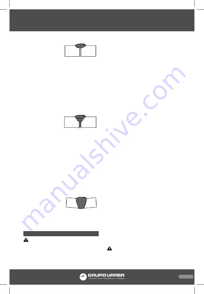
3. Inadequate: Weld does 
not contact the joint 
fully, just on the surface.
a. Work pieces too thick/

close; Joint design 
must allow weld to reach bottom of groove 
and allow proper welding procedures. 

b. Incorrect welding technique; Maintain 

1/2”or less stick out. Keep arc on leading 
edge of weld puddle. Hold gun at proper 
angles.

c. Insufficient weld material; Increase wire feed 

speed.

d. Insufficient weld heat; Reduce Welding 

Speed.

 NOT ADHERING PROPERLY
Gaps present between 
weld and previous bead 
or between weld and 
workpiece.  
a. Dirty workpiece; Make certain that work-

piece is clean and free from oil, coatings, 
and other residues.

b. Insufficient weld material; Increase wire 

feed speed.

c. Incorrect welding technique; Place stringer 

bead at correct place in joint. Adjust work-
piece position or weld angle to permit 
proper welding at bottom of work- piece. 
Pause briefly at sides when using a weave 
bead. Keep arc on leading edge of weld 
puddle. Hold gun at proper angles and 
make tack welds to help hold pieces.      

BENT AT JOINT
a. Improper clamping; 

Make sure that pieces 
are clamped securely 
in place.

b. Excessive heat; Weld a small portion and al-

low cooling before proceeding. Reduce wire 
feed speed.

MAINTENANCE

 WARNING: Make sure the Power Switch of 

the Plasma welder is in its “OFF” position and 
that the tool is unplugged from the electri-
cal outlet before performing any inspection, 
maintenance, or cleaning procedures.

1. Periodically open the Access Panel from the 
machine and, using compressed air, blow out 
all dust and debris from the interior
2. Always store the welder in a clean, dry, safe 
location out of reach of children and other un-
authorized people.

For optimal weld quality, clean and inspect the 
contact tip and nozzle before each use, as fol-
lows: Nozzle Inspection, cleaning;
a. Turn the Nozzle (1b) counterclockwise while 

pulling to remove.

b. Scrub the interior of the Nozzle clean with 

a wire brush.

c. Examine the end of the nozzle(1a).The end 

should be flat and even, If the end is uneven, 
chipped, melted, cracked, or otherwise dam-
aged, the nozzle will adversely effect the 
weld and should be replaced.

d. Reinstall the Nozzle (1a) after inspecting and 

cleaning the Contact Tip.

Contact tip Inspection, cleaning, and replace-
ment
a. Make sure the entire Welding torch is com-

pletely cool before proceeding.

b. Remove the nozzle as explained above. Then 

remove the contact tip.

c. Scrub the exterior of the contact tip clean 

with a wire brush. Check that the contact tip 
is the proper type for the wire size used.

d. Examine the hole at the end of the contact 

tip for the following problems:
Shape: The hole should be an even circle, 
and should not be oblong or have any 
bulges in it.
Size:  The Contact Tip will decrease in effi-
ciency as the center hole enlarges. A Contact 
Tip that measures 150% or more the original 
size* should be replaced. (*.045” or more 
for .030” tips;  .035” or more for .023 tips).

e. If any problems are noted with a Contact Tip 

(1b), it is recommended to have it replaced.

When inspection and maintenance is complet-
ed, reinstall the Contact Tip (1b) and Nozzle 
(2b).

MAINTENANCE

 WARNING: Make sure the Power Switch of 

the Welder is in its “OFF” position and that the 
tool is unplugged from the electrical outlet be-

SOLM1020 manual.indd   25

26/11/15   2:53 p.m.

Summary of Contents for SOLM1020

Page 1: ...nual antes de operar esta herramienta WARNING Read understand and follow the safety rules in this manual before operating this tool Soldadora Inverter MIG Inverter MIG Welder SOLM1020 Manual de Usuari...

Page 2: ...uidados de las herramientas el ctricas Advertencias de seguridad para soldadoras MIG Caracter sticas Instrucciones de operaci n Mantenimiento Solucionador de problemas Especificaciones t cnicas Garant...

Page 3: ...calor aceite cantos vivos o piezas en movimiento Los cables da ados o enredados aumentan el riesgo de choque el ctrico Cuando maneje una herramienta el ctrica en el exterior use una prolongaci n de ca...

Page 4: ...Las herramientas el ctricas se reparan antes de su uso cuando est n da adas Muchos acciden tes son causados por herramientas el ctricas pobremente mantenidas Mantenga las herramientas de corte afilad...

Page 5: ...ignici n de materiales com bustibles del otro lado coloc ndolos en un lugar seguro Si el traslado de los materia les combustibles no fuera posible designe a alguien para que vigile los riesgos de ince...

Page 6: ...se en zonas especificas y claramente marcadas con una leyenda que diga vac o 13 Nunca utilice aceite o grasa en cualquier conector de entrada salida o v lvulas de los cilindros 14 Utilice solamente la...

Page 7: ...mente el bot n 5 Cuando est s utlizando la modalidad MMA o TIG puede ajustar la corriente con esta perilla 6 Perilla de ajuste de voltaje para soldadura MIG 7 Perilla de ajuste de velocidad del cable...

Page 8: ...tam bi n debe colocar los rollos especiales de ali mentaci n de alambre ENSAMBLE DEL ALIMENTADOR DE ALAMBRE NOTA Al instalar el alambre de un tama o o composici n diferente usted tambi n tendr que ca...

Page 9: ...a Vuelva a colocar la boquilla 1b y qui te cualquier exceso de soldadura de alambre por sobre 1 2 pulgadas 9 Conecte una manguera y el acoplamiento del regulador de gas en un tanque de gas CO2 no incl...

Page 10: ...e el interruptor SOLDADURA TIG 1 Gire la perilla de ajuste de corriente para cumplir con las necesidades del trabajo 2 Mueva el selector de operaci n para MIG 3 Ponga el metal a soldar en la mesa de m...

Page 11: ...uniformemente el gas de protecci n a la zona de soldadura si el flujo es inconsistente no pueden proporcionar una protecci n adecuada de la zona de soldadura Boquillas m s grandes ofrecen una mayor pr...

Page 12: ...xtremo de la punta de contacto a la boquilla de gas est n relacionados con la dis tancia de la punta y tambi n var a con el tipo de transferencia y aplicaci n La orientaci n de la pistola tambi n es i...

Page 13: ...ermita que todos los componentes se enfr en completamente 1 Peri dicamente abra el panel de acceso de la m quina y usando aire comprimido sople el polvo y los residuos del interior 2 Guarde siempre la...

Page 14: ...a cabo por un t cnico cualificado Abrir la herramienta anular cualquier ga rant a y puede resultar en da os al equipo o lesiones personales No lo haga 9 Con una prueba a diario para cualquiera de los...

Page 15: ...a arreglar la situaci n EL ALAMBRE SE ALIMENTA PERO EL ARCO NO SE ENCIENDE Conexi n a tierra inadecuada Aseg rese de que la pieza de trabajo entra en contacto ade cuadamente con la pinza de tierra y q...

Page 16: ...the risk of electric shock PERSONAL SAFETY Stay alert watch what you are doing and use common sense when operating a power tool Don t use the tool if you are tired or under the influence of drugs alco...

Page 17: ...could re sult in a risk of injury SPECIFIC SAFETY RULES FOR TIG WELDERS 1 Maintain labels and nameplates on the tool These carry important information 2 Always wear the approved safety impact eye gog...

Page 18: ...sive vapors Clean and purge containers before applying heat Vent closed contain ers including castings before preheating welding i Only use compressed air to operate the Plasma Welder Never use other...

Page 19: ...minutes within a 10 minute period that a piece of equipment can safely operate This MIG welder has a 35 duty cycle which means that it may be used only 3 5 minutes at 200 Amps out of any 10 minute pe...

Page 20: ...quate fire extinguisher available if needed ASSEMBLY ATTACH AIR SUPPLY CAUTION Do not use an Argon Mixed pres sure regulator flow meter with CO2 Shielding gas To use CO2 Shielding gas you must install...

Page 21: ...inning please read and understand all the safety precautions staring on page 1 and especially the section Specific Safety Rules MIG WELDING 1 Turn the Current Adjustment Knob to meet the needs of the...

Page 22: ...he Welding Wire into the weld ing surface to ignite the arc This will cause the Welding Wire to stick to the workpiece 17 For a narrow weld you can usually draw the Welding Wire in a steady straight l...

Page 23: ...ternating current can be used There are four primary methods of metal transfer in GMAW called globular short circu iting spray and pulsed spray each of which has distinct properties and corresponding...

Page 24: ...shielded metal arc welding the operator must frequently chip off slag and change welding electrodes GMAW requires only that the operator guide the welding gun with proper position and orientation alo...

Page 25: ...st and debris from the interior 2 Always store the welder in a clean dry safe location out of reach of children and other un authorized people For optimal weld quality clean and inspect the contact ti...

Page 26: ...SHOOTING Be CERTAIN to shut off the TIG Welder and disconnect it from power and air before ad justing cleaning or repairing the unit A tech nician should discharge all capacitors before performing and...

Page 27: ...o check that the tip is not dirty this would prevent a good connection If needed replace Contact Tip with proper size and type WIRE FEEDS BUT SHIELDING GAS DOES NOT FLOW Empty Gas cylinder Check gas c...

Page 28: ...dified by unauthorized or unqualified person Urrea Herramientas Profesionales S A de C V garantiza este producto por el termino de 1 a o en sus piezas componentes y mano de obra con tra cualquier defe...

Reviews: