background image

DS1092-090


52


3.2.1 WALL 

MOUNTING 




Before starting installation, check that all devices to be connected are not powered. 



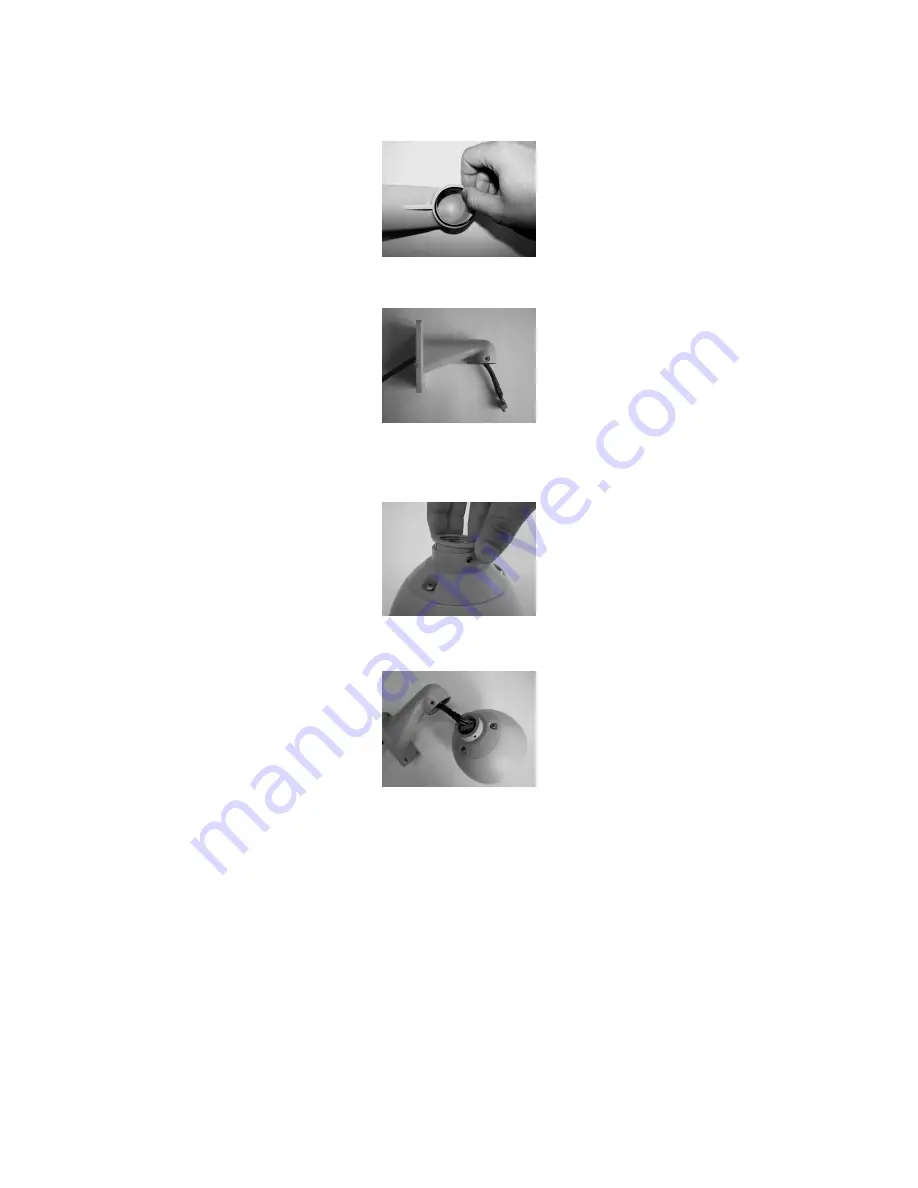
Place on the wall mounting bracket the provided o-ring, in the suitable seat.  




Fit the dome connection cable, provided, into the bracket, until it comes out on the opposite side. 




Put the provided junction ring in the upper seat of the dome, taking care that the three holes on the 
dome match the three holes on the ring, using the references on both the sides.    




Connect the cable terminal block to the dome terminal block, as shown in the figure. 


Summary of Contents for THERA 5 Ref.1092/602

Page 1: ...090 Mod 1092 THERA 5 MINIDOME P T Z ANTIVANDALO DA ESTERNO CON ZOOM 10X THERA 5 P T Z VANDAL PROOF OUTDOOR MINIDOME WITH 10X ZOOM Sch Ref 1092 602 MANUALE DI INSTALLAZIONE ED USO INSTALLATION AND USER...

Page 2: ...alle visualizzazioni 19 4 5 3 Impostazioni da menu relative alle programmazioni principali Control Options 20 4 5 4 Impostazioni da menu relative alle programmazioni principali Diagnostic Options 21...

Page 3: ...il contenuto non presentino danni visibili Se alcune parti non sono presenti o risultano danneggiate contattare immediatamente il rivenditore In questi casi non tentare di utilizzare il dispositivo S...

Page 4: ...oni del manuale di installazione ed uso e utilizzare solo gli accessori raccomandati e forniti come accessori alla minidome Aerazione Non posizionare mai la minidome vicino o sopra radiatori o fonti d...

Page 5: ...pericoli Controllo di sicurezza Una volta completato qualunque intervento d assistenza o di riparazione sul sistema video richiedere al tecnico dell assistenza di eseguire i controlli di sicurezza per...

Page 6: ...almeno una tastiera di comando Questa oltre alla configurazione dei parametri di funzionamento gestisce le funzionalit di brandeggio sull asse orizzontale 360 continui e sull asse verticale 180 di zoo...

Page 7: ...Inserire il cavo di collegamento della dome in dotazione all interno della staffa fino a farlo fuoriuscire dalla parte opposta Posizionare l anello di raccordo in dotazione nella sede superiore della...

Page 8: ...di far passare il cavo attraverso l asola situata nella staffa o praticare un ulteriore foro sulla parete in corrispondenza del cavo in uscita dalla staffa di diametro sufficiente al passaggio del ca...

Page 9: ...ollegamenti relativi alla linea RS485 inserendo attraverso il foro pi grande presente sul lato inferiore corredato di pressa cavo un cavo a due conduttori della lunghezza e sezione adeguati allo scopo...

Page 10: ...o il coperchio di protezione Riposizionare il coperchio di protezione Richiudere il Power Box nel modo inverso alla sua apertura Inserire il cavo di collegamento della dome in dotazione all interno de...

Page 11: ...aiutandosi con i riferimenti presenti su entrambe le parti Collegare la morsettiera del cavo alla morsettiera della dome come indicato in figura Bloccare la staffa alla dome utilizzando le tre viti c...

Page 12: ...edi COLLEGAMENTO LOGICO DELLA LINEA RS485 collegare una resistenza da 120 Ohm w non in dotazione sulla linea RS485 Effettuare i collegamenti come indicato nel DETTAGLIO DEI COLLEGAMENTI Collegare l al...

Page 13: ...entazione di THERA 5 Se il cavo troppo piccolo sull apparecchiatura la caduta di tensione da esso determinata pu causare un funzionamento improprio La seguente formula determina la tensione fornita a...

Page 14: ...LCO D COMM 9600 ADDR 01 SW version X XX Nota Bene Prendere nota della versione SW in caso di richiesta di assistenza tecnica 2 Al termine della fase di calibrazione la dome si pone in fase di attesa c...

Page 15: ...ato in dettaglio come usare i comandi con alcuni esempi applicativi Uso di un tasto singolo La pressione di un singolo tasto pu provocare un azione sulla dome Ad esempio il comando seguente provoca un...

Page 16: ...a che il valore di massima velocit di rotazione ottenibile agendo sui tasti numerici non sempre uguale a quello impostato nelle opzioni di funzionamento Esso infatti dipende dal valore dell opzione PR...

Page 17: ...uesto caso l autofocus interverr nuovamente a regolare il fuoco in maniera automatica Per ulteriori dettagli sulla regolazione della messa a fuoco e sulle varie opzioni si rimanda alla sezione opportu...

Page 18: ...valori di Preset impostati Avvertenza valori di Preset memorizzano le coordinate di un sistema di riferimento angolare per cui possibile che dopo un prolungato uso di comandi di brandeggio l origine d...

Page 19: ...lo scegliendo DOME INFORMATION si ottengono le informazioni relative al modulo protocollo baudrate all indirizzo della dome alla versione Queste informazioni non possono essere variate in questo menu...

Page 20: ...nzione di tilt risultano invertiti VectorScan Still ON OFF FUNZIONE NON ABILITATA Auto Focus ON OFF PTZ Z Se attivato con ON la Dome eseguir in automatico il controllo della messa a fuoco delle immagi...

Page 21: ...seguite dall utente La dome esegue un riposizionamento 4 5 5 IMPOSTAZIONI DA MENU RELATIVE ALLE PROGRAMMAZIONI SECONDARIE CAMERA OPTIONS Dal menu di primo livello scegliendo CAMERA OPTIONS e relativi...

Page 22: ...ire dal menu principale e tornare al men OSD 4 5 7 DESCRIZIONE DELLE VOCI DI MENU 4 5 7 1 Cam title assegnazione di un nome alla dome Questa funzione consente di nominare la dome e di visualizzare il...

Page 23: ...co in condizioni di luce estreme inquadrature con grandi variet di colori ma assenza di bianco in ambienti chiusi con illuminazione artificiale fluorescente colorata ecc Nota Bene Si consiglia di non...

Page 24: ...alore Spiegazione MODE MANUAL AUTO ONE PUSH Consente di selezionare il modo di messa a fuoco della dome Vedi oltre ZOOM TRK ON OFF Se l opzione selezionata ON l ottica della dome eseguir in continuo l...

Page 25: ...WIDE Press SET to Return Utilizzando I tasti FOCUS e ZOOM possibile eseguire le regolazioni desiderate TELE avvicina l immagine WIDE allarga l immagine Premere CLOSE per tornare al menu precedente Se...

Page 26: ...uente sottomenu EXPOSURE SETUP BRIGHTNESS 41 IRIS MANUAL SHUTTER MANUAL AGC NORMAL SSNR HIGH SENS UP OFF END Opzione Valore Spiegazione BRIGHTNESS 0 100 Consente di regolare la luminosit delle immagin...

Page 27: ...a dome potendo scegliere fra valori che variano fra 1 50 e fix 2x Selezionare END e premere CLOSE per tornare al menu precedente AGC CONTROLLO AUTOMATICO DEL GUADAGNO L AGC un circuito elettronico che...

Page 28: ...l regolazioni speciali Questa funzione consente di variare le funzioni relative ai parametri della dome Selezionando questa voce di menu e premendo il tasto OPEN si accede al seguente sottomenu SPECIA...

Page 29: ...MENTE NON DISPONIBILE COLOR Con questa opzione le immagini riprese dalla dome risultano sempre a colori B W Con questa opzione le immagini riprese dalla dome risultano sempre in bianco nero IMAGE ADJ...

Page 30: ...Display Consente di accedere a tutte le funzioni relative ai Pattern quali memorizzazione selezione nomenclatura e cancellazione Vedi oltre Sector Setup Number Name Pan Start POS Pan End POS Tilt Star...

Page 31: ...schermata che consente di nominare il preset Vedi oltre Name Display ON OFF Questa operazione se selezionata in ON consente di vedere a monitor il mome precedentemente memorizzato e associato al pres...

Page 32: ...memorizzare Utilizzare i tasti freccia per spostarsi nella posizione nella quale si vuole inserire il dato 1 il numero di azione possibile inserire un massimo di 16 azioni Name il tipo di azione selez...

Page 33: ...due volte OPEN possibile accedere alla schermata che consente di battezzare il pattern Vedi oltre Program a Pattern Questa opzione consente di memorizzare i pattern Posizionandosi per mezzo dei tasti...

Page 34: ...nando SECTOR SETUP e premendo OPEN si accede al seguente sottomenu Opzione Valore Spiegazione Number 1 8 Questa opzione consente di identificare i settori che si vogliono memorizzare E possibile selez...

Page 35: ...a inquadratura di partenza da memorizzare possibile vedere a monitor anche le coordinate relative alla inquadratura visualizzata Premere nuovamente OPEN per confermare la memorizzazione del punto di p...

Page 36: ...onando MASK EDIT e premendo si visualizza a monitor la zona di riservatezza selezionata precedentemente con Number Utilizzando i tasti freccia possibile spostare la zona nella posizione desiderata Uti...

Page 37: ...azione abbia inizio AutoScan Al termine dell azione eseguita dall utente la dome esegue una scansione orizzontale di 360 dopo il tempo stabilito PARK TIME prima che l azione abbia inizio Park Action R...

Page 38: ...o IL TASTO FRECCIA DESTRA si accede al seguente sottomenu Opzione Valore Spiegazione Start Position 0 0 359 9 0 0 90 0 Questa opzione consente di memorizzare le coordinate di inizio del settore relati...

Page 39: ...ssibile accedere alla schermata che consente di battezzare i contatti prescelti Label Display ON OFF Questa opzione se settata in ON consente di visualizzare sul monitor il nome precedentemente memori...

Page 40: ...one si vuole attivare Il numero selezionabile della singola azione varia in funzione della azione precedentemente selezionata da 1 a 165 esclusi i non programmabili per i Preset da 1 a 6 per i VectorS...

Page 41: ...rnamente alla dome 4 Eseguite le regolazioni volute utilizzando il piccolo cacciavite in dotazione 5 Posizionare la cupola interna sul supporto facendo coincidere le alette di tenuta della cupola stes...

Page 42: ...11 ON ON OFF ON OFF OFF OFF OFF 12 OFF OFF ON ON OFF OFF OFF OFF 13 ON OFF ON ON OFF OFF OFF OFF 14 OFF ON ON ON OFF OFF OFF OFF 15 ON ON ON ON OFF OFF OFF OFF 16 OFF OFF OFF OFF ON OFF OFF OFF 17 ON...

Page 43: ...zione variando la configurazione dei dipswitch numero 3 e 4 situato sulla scheda elettronica della dome seguendo le posizioni indicate NOTA BENE Si consiglia la selezione del protocollo PELCO D alla b...

Page 44: ...nza del quarto VectorScan CALL 87 Abilita la partenza del quinto VectorScan CALL 88 Abilita la partenza del sesto VectorScan CALL 90 Abilita il men CALL 91 Richiama l ultima posizione della dome mante...

Page 45: ...le rumore 50 dB Risoluzione Colore 500 TVL B N 570 TVL Messa a fuoco Automatica Manuale Sincronizzazione Interna Standard video PAL Range di rotazione asse orizzontale 360 continui Range di rotazione...

Page 46: ...Pelco D Data rate 2400bps 4800bps 9600bps selezionabili tramite dip switch NOTA BENE Il modulo camera di THERA 5 utilizza la tecnologia DSS Digital Slow Shutter In questo modulo detto Sens Up le impo...

Page 47: ...ng procedures via the menu Control Options 65 4 5 4 Settings of main programming via the menu diagnostic options 66 4 5 5 Settings of secondary programming via the menu camera options 66 4 5 6 Menu st...

Page 48: ...isibly damaged Contact the retailer immediately if parts are either missing or damaged Do not attempt to use the device in this case Send the product back in its original packing if it is damaged 1 2...

Page 49: ...dition to seriously damaging the product Follow the instruction manual and only use the recommended accessories for the camera for installation and set up Ventilation Never position the camera near or...

Page 50: ...can cause fires electrical shocks and other dangers Safety checks After any servicing intervention or repair to the video system ask the technician to run a safety check to ensure that everything is w...

Page 51: ...r a correct operation at least one control keypad is needed This keypad manages the configuration of operating parameters and the function of pan 360 continuous and tilt 180 motorized zoom recall and...

Page 52: ...the suitable seat Fit the dome connection cable provided into the bracket until it comes out on the opposite side Put the provided junction ring in the upper seat of the dome taking care that the thre...

Page 53: ...that the cable goes through the slot in the bracket or make another hole on the wall in order to allow the passage of the cable The diameter of this hole must be large enough for the passage of the co...

Page 54: ...e the connections for the RS485 line Insert in the largest hole on the lower side provided with grommet a 2 wire cable of suitable length and section see Requirements for connection cables This cable...

Page 55: ...the terminal pins on the card after removing the protection lid Put again the protection lid Close again the Power Box Fit the dome connection cable provided into the bracket until it comes out on the...

Page 56: ...he ring using the references on both the sides Connect the cable terminal block to the dome terminal block as shown in the figure Fix the bracket to the dome using the three provided round head screws...

Page 57: ...line see RS485 LINE LOGIC CONNECTION connect a 120 Ohm w resistor not provided in parallel to the RS485 line Make connections as shown in CONNECTIONS DETAILS Connect the power supply unit to the mains...

Page 58: ...supply voltage for THERA 5 If the cable diameter is too little the voltage dropout can cause malfunction The following formula shows the voltage provided to THERA 5 according to the cable dimension 5...

Page 59: ...L PELCO D COMM 9600 ADDR 01 SW version X XX Note Write down the SW version if technical assistance is required 2 Once the calibration phase is completed the dome goes in waiting mode and operates acco...

Page 60: ...es below explain how to use commands with some application examples Use of a single button A single button pressed can have an effect on the dome For example with the following command the shot is enl...

Page 61: ...in the operation options It depends on the value of the option PROPORTIONAL SPEED in the menu CONTROL OPTIONS If this option is ON the max rotation speed that can be reached by pressing the numeric b...

Page 62: ...command In this case the autofocus will automatically adjust the focus For further details about focus adjustment and different options see the section concerning operation modes settings NOTE Autofoc...

Page 63: ...owered Factory default restore operation deletes all the stored presets Notice angular coordinates are stored in the Preset values After long use of pan and tilt commands the alignment between mechani...

Page 64: ...RODUCT INFORMATION MENU Select DOME INFORMATION from the first level menu to have information about module protocol baud rate dome address version This information can not be changed in this menu 4 5...

Page 65: ...k commands for tilt function are reversed VectorScan Still ON OFF FUNCTION NOT ENABLED Auto Focus ON OFF PTZ Z If activated with ON the dome will automatically control the image focus If activated wit...

Page 66: ...me goes back to its default position 4 5 5 SETTINGS OF SECONDARY PROGRAMMING VIA THE MENU CAMERA OPTIONS From the first level menu select CAMERA OPTIONS and its submenus to access camera menus for pro...

Page 67: ...ain menu and go back to the OSD menu 4 5 7 MENU ITEMS DESCRIPTION 4 5 7 1 Cam title assigning a name to the dome This function allows to give a name to the dome and display this name in the desired po...

Page 68: ...ured artificial lighting etc Note It is recommended not to use this mode if not strictly necessary Use the arrow buttons to move on the desired item and increase or decrease the displayed value After...

Page 69: ...form a continuous autofocus ZOOM SPEED FAST SLOW It allows to select the dome focusing speed The function can NOT be activated if the option MODE is AUTO and the option ZOOM TRK is ON see below D ZOOM...

Page 70: ...M POS SETUP TELE WIDE Press SET to Return Use the buttons FOCUS and ZOOM to perform the desired adjustments TELE zoom in WIDE zoom out Press CLOSE to go back to the previous menu Select END and press...

Page 71: ...to access the following submenu EXPOSURE SETUP BRIGHTNESS 41 IRIS MANUAL SHUTTER MANUAL AGC NORMAL SSNR HIGH SENS UP OFF END Option Value Description BRIGHTNESS 0 100 It allows to adjust image bright...

Page 72: ...s to change the lens opening and choose values from 1 50 to fix 2x Select END and press CLOSE to go back to the previous menu AGC GAIN AUTOMATIC CONTROL AGC is an electronic circuit which amplifies th...

Page 73: ...allows to change the functions concerning dome parameters Select this menu item and press the button OPEN to access the following sub menu SPECIAL SETUP USER PRESET OFF PRIVACY OFF DAY NIGHT AUTO1 SY...

Page 74: ...are always in colour mode B W With this option the images captured by the dome are always in black white mode IMAGE ADJ Select IMAGE ADJ and press OPEN to access the following submenu IMAGE SETUP FREE...

Page 75: ...Sector Setup Number Name Pan Start POS Pan End POS Tilt Start POS Name Display It allows to define a certain sector and give it a name in this way the area can be identified each time it is displayed...

Page 76: ...to give a name to the stored presets Press twice OPEN to access the screen where to give a name to the preset see below Name Display ON OFF If ON this operation allows to display on the monitor the na...

Page 77: ...enu where it is possible to define the parameters of the VectorScan to be stored Use the arrow buttons to move the cursor in the position where the data must be entered 1 is the action number up to 16...

Page 78: ...to the stored patterns Press OPEN twice to access the screen where to give a name to patterns see below Program a Pattern This option allows to store patterns With the arrow buttons move on the initi...

Page 79: ...ors to be stored Up to 8 sectors max can be selected Name This option allows to give a name to the stored sectors By pressing twice OPEN on the display appears the screen where it is possible to edit...

Page 80: ...ON OFF If enabled ON this function allows to see on the monitor the name previously stored and associated to the displayed sector NAME Select NAME and press OPEN to access the following submenu where...

Page 81: ...ng zone MASK EDIT Select and press MASK EDIT to display on the monitor the masking zone previously selected with Number Use the arrow buttons to move the zone in the desired position Use the buttons T...

Page 82: ...ction starts AutoScan At the end of the action performed by the user and after a configured time PARK TIME the dome will execute a 360 horizontal scan before the action starts Park Action RepeatLast A...

Page 83: ...to store the sector coordinates Select LIMIT OPERATION and press the right arrow button to access the following submenu Option Value Description Start Position 0 0 359 9 0 0 90 0 This option allows to...

Page 84: ...tivation parameters see below Channel Enable ON OFF If set to ON this option enables the previously described functions ACTION SETUP Select ACTION SETUP and press OPEN to access the following submenu...

Page 85: ...he dome 4 Perform the desired adjustments using the provided little screwdriver 5 Place the internal cover on the stand until the fixing lugs of the dome match the holes on the stand and rotate clockw...

Page 86: ...OFF OFF OFF OFF 12 OFF OFF ON ON OFF OFF OFF OFF 13 ON OFF ON ON OFF OFF OFF OFF 14 OFF ON ON ON OFF OFF OFF OFF 15 ON ON ON ON OFF OFF OFF OFF 16 OFF OFF OFF OFF ON OFF OFF OFF 17 ON OFF OFF OFF ON...

Page 87: ...elected changing the configuration of the dip switches number 3 and 4 on the electronic card of the dome following the positions indicated below NOTE It is suggested to select PELCO D protocol at 9600...

Page 88: ...ALL 88 Starts the sixth VectorScan CALL 90 Enables the menu CALL 91 Recalls the last dome position kept for at least 5 seconds PRESET 94 Performs the dome reset CALL 101 Starts a 360 scan operation CA...

Page 89: ...Scan Pan Scan Frame Scan Sens up Auto Iris Auto flip On screen menu Titolazione Preset On Screen Display OSD VectorScan sequences of functions and Presets that can be activated 6 VectorScan x 16 func...

Page 90: ...DS1092 090 90 NOTE...

Page 91: ...DS1092 090 91 NOTE...

Page 92: ...OVO NA V Nazionale delle Puglie 3 Tel 081 193 661 20 Fax 081 193 661 04 30030 VIGONOVO VE Via del Lavoro 71 Tel 049 738 63 00 r a Fax 049 738 63 11 66020 S GIOVANNI TEATINO CH Via Nenni 17 loc Sambuce...

Reviews: