background image

DS1098-019A


30


3.4.4.4 

Email set 


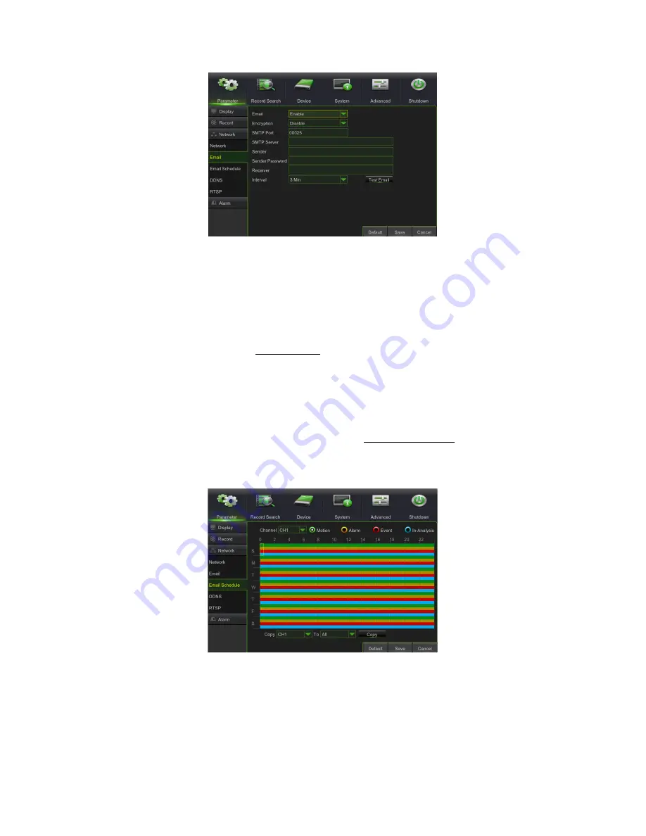
Click on the [Main menu Parameter Network Email] option to access the email setup interface shown here. 


SSL: this is a secure link transfer protocol. Via SSL it is possible to encode the communicated information (including 

your email) to prevent hackers from reading emails, transmitted data and even passwords. 

Set SSL to “On” on the Gmail.com server and to “Off” on another email server. 


SMTP Port:

 this indicates a port type for email transmission via Simple Message Transfer Protocol (SMTP). The port 

number for most emails is 25, except for the Gmail server (port number: 465). 


SMTP server:

 this indicates the address of the server used. 


Sender address:

 this is the sender's email address. The email address must be compatible with the server used. In 

other words, if the email address used is

 [email protected], the server must be smtp.gmail.com. 


Sender Pwd: 

this sets the password assigned to the email account by the sender. 


Receiver address:

 this is the receiver's email address. The email address is used to receive the image transmitted 

by the NVR alarm. Delete all the received images as soon as possible to prevent overloading your email account. 


Interval:

 the time for sending the email with attachments can be set in minutes. 


Note: 

to  ensure  correct  operation,  it  is  advisable  to  configure  a  user  account  (address  and  sender  password)  with  the  same 
address as the SMTP server. For example, if the email address used is [email protected], the SMTP address must be 
“smtp.dominio.it”.


The  Events  Detection  emails  sent  can  be  programmed  per  Channel,  day  of  the  week  and  according  to  the  event  type 
(Motion, Alarm or Event), as shown below:


3.4.4.5 

DDNS Set 

 
DDNS (Dynamic DNS) is a service used to record a domain name and floating IP address with the DDNS server for the 
domain name to be routed towards the IP address even if it is modified in a dynamic IP system. 
The user can access a remote NVR using DDNS on the three previous types (Static, DHCP and PPPoE).  
 
Read the description under the following figures for this menu page: 


Summary of Contents for 1098/316

Page 1: ...DS1098 019A Mod 1098 NVR H 265 WITH HDMI NVR 4K H 265 PRO SERIES 8 Ch Ref 1098 318 16 Ch Ref 1098 316 16 Ch with PoE Ref 1098 316P 32 Ch Ref 1098 332 USER MANUAL...

Page 2: ...Interface and Pop up Menu 13 3 2 Guide to the Main Menu 15 3 3 Main Menu 17 3 4 Parameter settings 17 3 4 1 Display 18 3 4 1 1 IP Channels IP cameras 18 3 4 1 2 Live 20 3 4 1 3 Output 21 3 4 1 4 Imag...

Page 3: ...3 Stream Switch 55 3 5 4 Preview Policy 55 3 5 5 Start Sequence 56 3 5 6 Mute 56 3 5 7 Playback 56 3 5 8 Shut Down 56 3 6 Pop up menu for IP channel 56 3 6 1 Stream Switch 56 3 6 2 Manual Record 56 3...

Page 4: ...5 Remote Settings 106 5 1 1 6 Alarm 106 5 1 1 7 Device 107 5 1 1 8 Help 108 5 2 P2P function 109 6 NVR Specifications Rev 1098 318 1098 316 1098 332 Pal Format 111 7 NVR Specifications Rev 1098 316P P...

Page 5: ...e and monitoring via mobile phone Network transmission of the Main Stream Sub Stream and Mobile Stream on the IP channels Remote control via browser via mobile and via Urmet UVS Client Software Remote...

Page 6: ...supports Urmet UVS client software MP live monitoring and zoom in out automatic sequence and PiP display Record Video compression standard H 265 adjustable recording quality resolution and frame rate...

Page 7: ...Do not install the device in a place where it could be exposed to dampness or water Do not direct a jet of water onto the device to avoid risk of fire electrocution or mechanical failure Stop using th...

Page 8: ...ents Protect the device from bumps and jolts to ensure proper recording of images 1 3 7 PRIVACY AND COPYRIGHT The digital video recorder Series PRO Ref 1098 318 Ref 1098 316 Ref 1098 316P Ref 1098 332...

Page 9: ...nd description 1 Power indicator PWR When the green LED is on it means that the NVR is powered correctly 2 IR receiver Receives the IR signal from the remote control 3 Hard disk indicator HDD When the...

Page 10: ...nnector e g USB mouse 5 USB 3 0 port USB 3 0 device connector for backups and firmware upgrades 6 HDMI port High definition HDMI port 7 VGA port VGA monitor connector e g PC monitor 8 Audio input Audi...

Page 11: ...tons Pressing buttons 9 and 0 has no effect 3 ALL Multiple viewing mode 4 Menu Open close main menu 5 MUTE Mute mode on off 6 SUBMENU Enter the Submenu 7 Arrow up volume adjustment 8 SEL Select Edit b...

Page 12: ...boxes Activate the drop down menu for support to enter Chinese characters special symbols numbers and letters to be used instead of Enter or Backspace Right click In live mode right click to view the...

Page 13: ...from the cameras In Live mode a double click on the live image of a channel will display it in full screen mode A second double click returns the image to multi split mode After the system has initia...

Page 14: ...vailable if a fish eye camera is connected Note when the hard disk HDD is not connected or an error has occurred the H character appears on the first channel of the live screen and an audible alarm ma...

Page 15: ...s Stream Switch Preview Policy Playback Mute Start Sequence Shutdown etc Parameter Display IP Channels Live Record Record Schedule Main Stream Sub Stream Mobile Stream Image Control Privacy zone Recor...

Page 16: ...trols General General DST NTP System Info Info Channel Info Record Info Users Log Advanced Maintain Events Shutdown Main Menu Shutdown Reboot Intelligent Schedule PID LCD SOD HDD Disk Group S M A R T...

Page 17: ...Menu button on the remote control to open the Main Menu interface as shown in section 2 1 The main menu screen can also be opened by clicking on the icon In Main Menu mode you can adjust device manage...

Page 18: ...nnel number of the IPC camera Edit To edit the name and position of the channels and other Channel connection parameters as shown in the figure State To display the IPC online state green IP Address D...

Page 19: ...k on Protocol Manage The following screen will appear The following parameters must be set Custom Protocol this defines the name of the RTSP protocol to associate with the IP camera The following fiel...

Page 20: ...bove Covert this is used to enable the Channel monitoring screen in Live mode AHD EQ image quality can be improved if EQ is enabled and the connected AHD camera supports the equalisation function Show...

Page 21: ...cription under the following figures for this menu page Channel this is used to select the channel number IR CUT Mode four modes are available GPIO Auto Colour B W and Video IR CUT Delay delays IR CUT...

Page 22: ...ed area 5 At the end of this operation right click to go back to the Privacy zone interface 6 Click on Save to save the previous setting 3 4 2 RECORDINGS SET UP 3 4 2 1 Record Read the description und...

Page 23: ...d Normal Record modes at the same time and to search for the recording file by setting the All Record filter 3 4 2 3 Main Stream Read the description under the following figures for this menu page Cha...

Page 24: ...ording to the frame frequency value selected for each IP channel with protocols other than ONVIF 3 4 2 5 Mobile Stream Read the description under the following figure for this menu page Channel this o...

Page 25: ...ording time for auto capture alarm possible values 5 sec 10 sec 30 sec 1 min 10 min 30 min 1 hour Manual Capture enables or disables the manual capture by the user function Copy this is used to copy t...

Page 26: ...th or without DDNS only if the access provider assigns a public IP address either static or dynamic to the router It is therefore advisable to previously verify this essential detail with the Internet...

Page 27: ...in the router configuration menu The ports set on the router must correspond to those of the NVR a Set different values on the NVR if the default ports of the NVR 80 9000 18600 are already in use in t...

Page 28: ...r name and password provided by ISP and set the Client port and the HTTP port At this point the NVR can be accessed remotely using the IP address acquired after recording a domain name and a Web port...

Page 29: ...select All or Both in the corresponding protocol column and save the aforesaid setting The previous procedure may vary from one router to the other according to the manufacturer 3 4 4 3 Switch only f...

Page 30: ...account by the sender Receiver address this is the receiver s email address The email address is used to receive the image transmitted by the NVR alarm Delete all the received images as soon as possib...

Page 31: ...ovided by the URMETDDNS server or the URMETDDNS2 server IMPORTANT NOTE A DDNS server other than URMETDDNS may be used Select the available options from the list For more details follow the instruction...

Page 32: ...R via the RTSP protocol 1 Enable the user name and the password for the NVR 2 Select the Network menu and check that the DHCP Mode option is set 3 On the NVR OSD menu Network RTSP enable the RTSP and...

Page 33: ...Trigger Alarm Out it is possible to select the Alarm Outputs that have to be activated automatically when the event is triggered The available options are o Local alarm output that is located on the...

Page 34: ...s used to set the appearance of the icon on the screen when a motion alarm is detected For icon types see section 4 Send Email this is used to send the alarm images to a specified email address Full s...

Page 35: ...the recordings on a specific date To run a video search highlight and select the date numeric field and then click on a given time period the system will start playback beginning with the first record...

Page 36: ...the available views will appear see figure below depending on the type of Fish Eye installation that was selected for LIVE For more details on the various viewing functions for each type of installati...

Page 37: ...fy the time interval on the day for which the search is made pre defined time setting 00 00 00 23 59 59 Channel this selects the channel s on which to make the search Type this selects the type of rec...

Page 38: ...ts on the last page Direct access add the recording page of the desired event in the provided box and click on the arrow button to go to the desired page Two types of Backup are available Quick Backup...

Page 39: ...backed up according to time Proceed as follows 1 enter the start and end time in the time editing box 2 Click on the Search button 3 Tick all files to be backed up 4 Click on the Backup button 3 4 9...

Page 40: ...ers Date Start End Channel Type Select the files you wish to save from those displayed in the list then press the Backup button to view the window shown in the image below select the desired video fil...

Page 41: ...and click on the icon or on the button to find select the backup file and then click on the open button 3 Highlight the selected file and click on the Play button Play button click on the icon to pla...

Page 42: ...he list Delete all files from the list Close and open the files in the list Advanced configuration click on the icon to set the acquisition path and the language if available as shown below IMPORTANT...

Page 43: ...define the period in days in which the recording file can be viewed in SEARCH RECORDING Select a value in days from the available options HDD Format Formatting the HDD will delete all data i e recordi...

Page 44: ...pe select the type of analysis to be performed on the HDD the possible values are Short or Whole Self check State this indicates the state of the check performed on the disc if run TEMP C Temperature...

Page 45: ...lly OFF focusing and zoom are deactivated Activate this option after having adjusted focus and zoom as required Cloud Storage the Cloud storage function can be activated Cloud type the Cloud type may...

Page 46: ...ove 3 4 11 3 Network Time Protocol NTP Service This service is used by the NVR to synchronise the system clock with the NTP Server Click on Main menu System General NTP to access the interface shown b...

Page 47: ...consists of 0 8 characters and has a fixed length of 8 numbers Note The password for the first login is 00000000 For safety reasons it is strongly advised to change the password after the first login...

Page 48: ...e mode Manual record this is used to start stop the recording manually Backup check this option to back up recording on all channels Live by ticking this option the user can view the images of all cha...

Page 49: ...Go to Main Menu System Record Info as shown in the following figure Here the user can view information on the various connected IPCs state mainstream substream motion detection privacy zone cruise et...

Page 50: ...ntain the following information Size of the recording file Date and time of the recording file The number name of the channel on which a particular operation was performed The user who exported the fi...

Page 51: ...NVR with the enable Administrator password Auto Reboot the user can set periodic automatic system reboots daily monthly weekly according to needs Upgrade this function decompresses the update file pa...

Page 52: ...matically restarted at the end of the upgrade The update will end after approximately 5 minutes It is advisable to load the default parameters after the upgrade The automatic maintain function will be...

Page 53: ...is used to send the alarm images to a specified email address Alarm Out this can be used to connect an external alarm sensor Select Enable or Disable Trigger Alarm Out it is possible to select the Ala...

Page 54: ...PD FD CC are mutually exclusive and cannot be activated at the same time 7 When the three algorithms PID LCD SOD are activated at the same time the most recently configured scene has validity 8 The v...

Page 55: ...e password is forgotten Note the parameters for sending emails described in paragraph 3 4 4 4 Email set must be correctly configured to use this function Useful note the Administrator has fully author...

Page 56: ...3 6 3 INSTANT PLAYBACK When Instant Playback is run the system shows the last five minutes of recording instead of the live video 3 6 4 ZOOM This allows you to zoom in on Live images by clicking the i...

Page 57: ...un the SET95 command first See the Speedome manual for the Speedome OSD 1 Select a camera on which to program a preset point 2 Position the camera in the required direction 3 Select Store to program t...

Page 58: ...ay The LIVE Display Mode currently shown on the screen can be changed depending on the type of installation selected Fisheye View wide angle obtained through the fisheye lens Panorama View fisheye vie...

Page 59: ...E screen of the local monitor At this point if the fisheye camera is mounted on the ceiling select the button from the Fish Eye installation menu shown in the figure below and save the settings The mu...

Page 60: ...DS1098 019A 60 2 3D cylinder as shown in the figure 3 180 Panorama view as shown in the figure 4 360 Panorama view as shown in the figure 5 4PTZ as shown in the figure...

Page 61: ...select the range of the corresponding PTZ line and drag to change the viewing angle as shown in the figure 7 Fisheye 8PTZ Fisheye View the different coloured areas represent different PTZ viewing ang...

Page 62: ...select the range of the corresponding PTZ line and drag to change the viewing angle as shown in the figure 9 360 Panorama View 8PTZ Panorama View the different coloured areas represent different PTZ...

Page 63: ...E screen of the local monitor At this point if the fisheye camera is mounted on a horizontal surface table select the button from the Fish Eye installation menu shown in the figure below and save the...

Page 64: ...DS1098 019A 64 2 3D Cylinder view as shown in the figure 3 180 Panorama view as shown in the figure 4 360 Panorama view as shown in the figure...

Page 65: ...shown in the figure 6 Fisheye 3PTZ Fisheye View the different coloured areas represent different PTZ viewing angles select the range of the corresponding PTZ line and drag to change the viewing angle...

Page 66: ...t the range of the corresponding PTZ line and drag to change the viewing angle as shown in the figure 8 360 Panorama View 3PTZ Panorama View the different coloured areas represent different PTZ viewin...

Page 67: ...viewing angle as shown in the figure 3 6 8 5 Wall installation Select the button on the multi function bar displayed at the bottom of the LIVE screen of the local monitor At this point if the fisheye...

Page 68: ...DS1098 019A 68 1 VR view double click with the right mouse button to begin navigation 2 Normal Panorama view as shown in the figure 4PTZ...

Page 69: ...select the range of the corresponding PTZ line and drag to change the viewing angle as shown in the figure 4 Fisheye 8PTZ Fisheye View the different coloured areas represent different PTZ viewing ang...

Page 70: ...select the range of the corresponding PTZ line and drag to change the viewing angle as shown in the figure 6 Panorama View 8PTZ Panorama View the different coloured areas represent different PTZ view...

Page 71: ...LIVE screen of the local monitor At this point if the fisheye camera is mounted on an inclined plane select the button from the Fish Eye installation menu shown in the figure below and save the settin...

Page 72: ...view as shown in the figure 3 Fisheye 3PTZ Fisheye View the different coloured areas represent different PTZ viewing angles select the range of the corresponding PTZ line and drag to change the viewi...

Page 73: ...the range of the corresponding PTZ line and drag to change the viewing angle as shown in the figure 5 4PTZ and Panorama view 3PTZ Panorama view the different coloured areas represent different PTZ vie...

Page 74: ...74 6 Panorama View 8PTZ Panorama View the different coloured areas represent different PTZ viewing angles select the range of the corresponding PTZ line and drag to change the viewing angle as shown i...

Page 75: ...perating system Vista Win 7 operating system Important note If the plug in cannot be downloaded check that the security level or the browser firewall settings are not too advanced Start IE Tools Inter...

Page 76: ...HTTP port associated with the NVR on the address bar e g http urmetvcc no ip org 81 If the HTTP port of the NVR is 80 it is sufficient to enter the URL of the NVR as follows http IP Address i e http...

Page 77: ...se the channel list in LIVE This is used to start or stop channel playback in LIVE Record icon once the recording is started it will be saved in a specified position Snapshot function this is used to...

Page 78: ...n and select Exit full screen 4 2 3 MANAGING FISH EYE CAMERAS Clicking the button on the control bar below the LIVE view opens the menu for selecting the Fish Eye installation mode ceiling wall table...

Page 79: ...to control the direction of the PTZ camera The central button is the Auto cruise control PTZ speed control bar Iris Focus and Zoom control Set Delete preset start arrow end square Cruise Note Use CAL...

Page 80: ...lour settings interface Hue This adjusts the video hue Bright This adjusts the video brightness Contrast This adjusts the video contrast Saturation This adjusts the video saturation This restores the...

Page 81: ...o check then tick Synchronous Playback and the channels you wish to play as shown below You can also decide which video stream to search MainStream or SubStream Then select the recording type Normal r...

Page 82: ...the screen when the mouse cursor is moved on the time axis Click on the or icon to zoom in or out of the ratio shown on the time bar as shown below 4 3 2 PLAYBACK CONTROL The playback control bar is...

Page 83: ...er having acquired the images they can be saved in a specific path as shown below The acquired files will be saved in bmp format 4 3 4 RECORDING FILE DOWNLOAD Click on the icon to access the interface...

Page 84: ...ected on the right hand side as shown in the figure For more details on the various viewing functions for each type of installation see section 3 6 8 Managing a Fish Eye camera Camera Management in th...

Page 85: ...added It can be used to quickly add a IPC online or to delete one that has been added as shown in the figure below It can also be used to quickly add a Cloud camera connected to the LAN network using...

Page 86: ...ettings for the local monitor can be changed via the Web interface in particular the monitor resolution and the display mode single Quad Eight Sixteen etc 4 Image Control if supported by the IP camera...

Page 87: ...o eliminate a privacy zone select it and then click on the Clear button and then on Save in the right hand corner 4 4 2 RECORD Click on the Record option to access its sub options Record parameters Sc...

Page 88: ...ates Normal record yellow indicates Motion detection red indicates I O triggered record 3 Stream setting this can be used to set the Mainstream Substream and Mobile Stream parameters as shown in the f...

Page 89: ...wing figures 4 4 1 NETWORK Open the Network option to access its sub options Network Sub stream Email and DDNS Configuration 1 The model supports three types of networks Static DHCP and PPPoE Static t...

Page 90: ...ent with the local settings of the NVR Set PPPoE type network the user name and the password must be consistent with the local settings of the NVR 2 Email setting click on the Email setting option to...

Page 91: ...at the DHCP Mode option is set On the OSD NVR menu Network RTSP enable the RTSP and Verify functions IMPORTANT NOTE for the RTSP UserName and RTSP Password options insert the user name and password us...

Page 92: ...ion this is used to configure Sensitivity Alarm out Alarm record Alarm Capture etc The detailed parameters must be consistent with the local settings of the NVR 2 I O Alarm this is used to configure I...

Page 93: ...d Send E Mail options 4 4 3 DEVICE Click on the Device option to access its sub options HDD and PTZ 1 HDD this is used to check the HDD state the overwrite time and to enable recording on the ESATA in...

Page 94: ...ed parameters must be consistent with the local settings of the NVR It is possible to select a digital protocol via network or an analogue protocol via RS 485 3 AF Controls for Auto focus IP Camera Mo...

Page 95: ...at DST and NTP as shown below The detailed parameters must be consistent with the local settings of the NVR 2 Users this is used to configure the user name and password as shown below The detailed par...

Page 96: ...vailable for IP cameras with ONVIF protocol as shown below Proceed as follows to update the system a Select the upgrade file as shown below The upgrade file is in sw format b Click on Start update the...

Page 97: ...ed parameters must be consistent with the local settings of the NVR 4 Maintain this is used to set automatic maintenance of the NVR system remotely as shown below The detailed parameters must be consi...

Page 98: ...DS1098 019A 98 5 Intelligent Algorithms programming and intelligent video analysis logs For details on the programming of these intelligent video analysis functions see the dedicated manual DS1093 XXX...

Page 99: ...ion can be used to set the recording file path Live recordings and Playback clip files the remote file download path the Snapshot path the file type H 265 and AVI and Internal as shown below 4 6 LOGOU...

Page 100: ...hat is compatible with all URMET devices both IPCam Codec H265 and NVR HVR all codecs Main features Multichannel audio video live streaming Multichannel remote playback Double stream playback Fisheye...

Page 101: ...onnect your iPhone iPad Android phone or Android tablet to the Internet via the 3G network or WIFI Start the application to access the Live menu To access the menu select the icon at the top left 5 1...

Page 102: ...of channels appears Select a channel which will be displayed in the main window Recording a live video stream You can record the stream while viewing a video in live mode Select and then the channel l...

Page 103: ...Z is short for Pan Tilt Zoom and refers to camera movement options Select to open PTZ mode this will bring up the PTZ control buttons on the live page Select the arrows to control camera movement from...

Page 104: ...layback in the main menu the play list will be displayed A channel from the device can be played remotely 1 Selecting a channel Select the Remote Playback button to open the device list as shown below...

Page 105: ...channel all dates with recordings will be marked with a dot Select a date to play the recordings from that day 5 1 1 3 Record You can record the stream while viewing a video in live mode as shown abov...

Page 106: ...98 019A 106 5 1 1 5 Remote Settings Controls on the remote device can be enabled such as sending e mail and enabling recording on the device 5 1 1 6 Alarm E mail notification of the devices can be ena...

Page 107: ...he start screen to open the interface shown below and manually add a device To add a new device select then Manual Adding Import Device via QR Code Online Device Device present on network enter the na...

Page 108: ...er for the the Mobile Software to work properly If the user does not configure the mobile device port the iUVS Mobile Software will not work To delete a device from list select the name of the device...

Page 109: ...e Apple Store or the iUVStab app from the Google Play Store Once the application has been downloaded from the store and installed the NVR can be added to the smartphone and viewed via a P2P connection...

Page 110: ...ort opening and forwarding o To view the IP camera in the local network LAN it can be added to the app using its IP address To know the local IP address of the IP camera see the menu page Network Menu...

Page 111: ...HDD Sata each HDD up to 8TB Video backup memory 2000 GB hard disk default External USB device CD DVD burner Eternal USB Network AVI file Playback modes PLAY SLOW FWD Frame by frame Web interface Multi...

Page 112: ...ing bandwidth Max 320Mbps ONVIF 2 3 YES Sub stream 1080P 1920x1080 720P 1280x720 VGA 640x480 CIF 320x240 real time Hard Disk interface Max 2 HDD Sata each HDD up to 8TB Video backup memory 2000 GB har...

Page 113: ...51 70 14 65 527 54 21 98 8 recording channels with 4K resolution 3840x2160 or 3000x3000 Variables to be set H 264 Codec H 265 Codec H 264 Bitrate in Kbps H 265 Bit rate in Kbps Frame rate in fps Time...

Page 114: ...6 38 1 10 40 58 1 69 4096 2560 6 8 32 97 1 37 52 75 2 20 3072 2048 4 5 43 96 1 83 65 94 2 75 2048 1536 1 3 65 94 2 75 87 92 3 66 1 recording channel with 4Mpx resolution 2592 1520 Variables to be set...

Page 115: ...4 1280 6 8 234 46 9 77 422 03 17 58 1536 768 4 5 351 70 14 65 703 39 29 31 768 512 1 3 703 39 29 31 1055 09 43 96 16 recording channels with 3 5Mpx resolution 2304 1296 Variables to be set H 264 Codec...

Page 116: ...40 68 5627 13 234 46 1024 512 4 5 4220 35 175 85 8440 70 351 70 768 384 1 3 5627 13 234 46 11254 26 468 93 4 recording channels with 1080P resolution 1920 1080 Variables to be set H 264 Codec H 265 Co...

Page 117: ...ps H 265 Bit rate in Kbps Frame rate in fps Time HD hours Time HD days Time HD hours Time HD days 1792 2048 24 25 301 45 12 56 263 77 10 99 1536 1792 20 23 351 70 14 65 301 45 12 56 1280 1536 16 19 42...

Page 118: ...to be set H 264 Codec Bitrate in Kbps Frame rate in fps HD time hours HD time days 2048 23 25 263 77 10 99 1792 20 22 301 45 12 56 1536 17 19 351 70 14 65 1280 14 16 422 03 17 58 1024 11 13 527 54 21...

Page 119: ...d to set passwords which are easy to remember and relatively secure In the case of particular security requirements avoid excessively obvious passwords like 000000 3 Q Can I add an IP camera with diff...

Page 120: ...and that the I O alarm is set to Always Off In addition refer to the respective settings of the HDD alarm 16 Q I cannot stop the recording by pressing the STOP button or clicking on Stop Recording in...

Page 121: ...as shown below before activating the connection to the PC Double click on the icon to open Internet Explorer Open Internet Explorer by double clicking on the icon The following page or the home page w...

Page 122: ...device e g http 192 168 36 40 or the address of the URMET DDNS portal http www urmetddns com or another URL for example http urmetvcc no ip org in the Add this website to the zone field Click on Add...

Page 123: ...alise and script ActiveX controls not marked as safe is set to Enable or Prompt Download signed ActiveX controls is set to Enable or Prompt Press OK each time to confirm and exit from Internet Options...

Page 124: ...DS1098 019A URMET S P A 10154 TORINO ITALY VIA BOLOGNA 188 C Tel 39 011 24 00 000 AUTO Fax 39 011 24 00 300 323 Technical area Customer service 39 011 23 39 810 http www urmet com e mail info urmet co...

Reviews: