background image

AC-PRO

®

 & AC-PRO-II

®

 B-292 Secondary Injection Test Set Instruction Manual                                                  Rev 1.1 

www.utilityrelay.com 


Figure 1: Test Set Exterior ............................................................................................................ 2


Figure 2: Test Set Case Interior .................................................................................................... 3


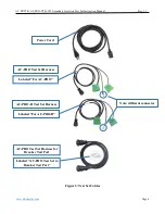
Figure 3: Test Set Cables .............................................................................................................. 4


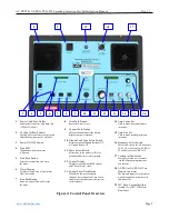
Figure 4: Control Panel Overview ................................................................................................ 5


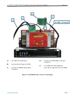
Figure 5: AC-PRO Breaker Test Set Connections ........................................................................ 8


Figure 6: AC-PRO-II Breaker Test Set Connections .................................................................... 9


Figure 7: AC-PRO Quick-Trip Testing Connections .................................................................. 18


Figure 8: AC-PRO-II Quick-Trip Testing Connections .............................................................. 19


Figure 9: AC-PRO Overload TCC .............................................................................................. 24


Figure 10: AC-PRO Unbalance TCC & Ground Fault TCC ...................................................... 25


Figure 11: AC-PRO Quick-Trip TCC ......................................................................................... 26


Figure 12: AC-PRO-II Overload TCC ........................................................................................ 27


Figure 13: AC-PRO-II Ground Fault TCC ................................................................................. 28


Figure 14: AC-PRO-II Quick-Trip TCC ..................................................................................... 29


Figure 15: AC-PRO-II Neutral Overload TCC ........................................................................... 30


For latest version, visit: 

http://www.utilityrelay.com/Side_Bar/Instruction_Manuals.html


Summary of Contents for B-292

Page 1: ......

Page 2: ... Time ST Pick Up Secondary Current 12 4 7 Short Time ST Pick Up Test 12 4 8 Short Time ST Test 13 4 9 Calculate Instantaneous I Pick Up Secondary Current 13 4 10 Instantaneous I Pick Up Test 14 4 11 Calculate Ground Fault GF Pick Up Secondary Current 14 4 12 Ground Fault GF Pick Up Test 15 4 13 Ground Fault GF Time Test 15 4 14 AC PRO Unbalance Testing 15 4 15 Calculate Neutral Overload NOL Pick U...

Page 3: ...reaker Test Set Connections 9 Figure 7 AC PRO Quick Trip Testing Connections 18 Figure 8 AC PRO II Quick Trip Testing Connections 19 Figure 9 AC PRO Overload TCC 24 Figure 10 AC PRO Unbalance TCC Ground Fault TCC 25 Figure 11 AC PRO Quick Trip TCC 26 Figure 12 AC PRO II Overload TCC 27 Figure 13 AC PRO II Ground Fault TCC 28 Figure 14 AC PRO II Quick Trip TCC 29 Figure 15 AC PRO II Neutral Overloa...

Page 4: ...t set will test the AC PRO or AC PRO II trip system with the exception of the CTs and associated wiring harness Important Secondary injection testing is not a substitute for primary injection testing that should be performed for any circuit breaker retrofit 2 0 Overview The basic function of the test set is to deliver an accurate level of AC current directly to the trip unit under test and to veri...

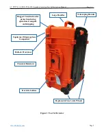
Page 5: ... www utilityrelay com Page 2 Figure 1 Test Set Exterior Copolymer Polypropylene Compound Chemical Resistant Replaceable Steel Axle Wheels Padlock Provisions Telescoping Handle Large Handles Rugged Construction for protection during operation transport and shipping Durable Latches ...

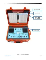
Page 6: ... PRO II B 292 Secondary Injection Test Set Instruction Manual Rev 1 1 www utilityrelay com Page 3 Figure 2 Test Set Case Interior Interior Panel Abbreviated Instruction Manual Long Time Test Chart Cable Storage ...

Page 7: ... 1 1 www utilityrelay com Page 4 Figure 3 Test Set Cables Power Cord AC PRO Test Set Harness AC PRO II Test Set Harness Labeled For AC PRO Labeled For AC PRO II Note different connector AC PRO Test Set Harness for Breaker Test Port Labeled AC PRO Test Set to Breaker Test Port ...

Page 8: ... Ground Return GF 11 Phase Select Switch Selects one of the phases A B C or ground fault as the test current path 12 Current Display Displays measured true RMS current and Current Preset value 13 Current Preset Push Button When held the current display indicates the setting of the Amp Coarse and Fine pots but does not send current to the trip unit 14 Amp Coarse Pot Used to make large adjustments i...

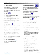
Page 9: ...ay 3 4 Start Push Button and LED The Start push button starts the test current flow to the trip unit and simultaneously starts the Timer 6 The green LED located above the Start push button indicates test current flow 3 5 Stop Push Button The Stop push button stops the test current flow and simultaneously freezes the Timer 6 3 6 Test Current display The Test Current display indicates the true RMS t...

Page 10: ...y Selector The Frequency selector switch is used to select the AC test current frequency This is used to select either 25 40 50 or 60 Hz for AC PRO The selections for AC PRO II are 50 or 60 Hertz 3 12 Contrast Push Button The Contrast push button changes the contrast of both the Timer 6 and Current 12 displays The push button should be pushed until the desired contrast is seen in the displays 3 13...

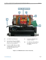
Page 11: ... com Page 8 A AC PRO Test Set Harness B Test Set Power Plug to AC PRO C Test Set AC PRO Harness Main Connector D Test Set AC PRO Harness Actuator Connector E Circuit Breaker Wiring Harness previously connected to the AC PRO Figure 5 AC PRO Breaker Test Set Connections C E D AC PRO on breaker B A ...

Page 12: ...Remove the cover not pictured to gain access to the connector H Test Set AC PRO II Harness Main Connector Remove the wire guard not pictured to gain access to the connector J Test Set AC PRO II Harness Actuator Connector K Circuit Breaker Wiring Harness previously connected to the AC PRO II Figure 6 AC PRO II Breaker Test Set Connections F G H J K AC PRO IITM on breaker ...

Page 13: ...RO Connect the small round connector on the Test Harness B to the 24 VAC auxiliary power jack AC PRO II Connect the white rectangular connector on the Test Harness G to the 24VDC Aux Power input after removing the connector cover 5 Connect the previously removed breaker wiring harness connector to the male ten position terminal block on the Test Harness Actuator Connector D or J if installed on a ...

Page 14: ...me way 4 5 Long Time LT Time Test To test the LT time delay trip 1 The first step is to select a test current For example three times the LT pick up 3X on the TCC in Figure 9 or Figure 12 The desired test current is then 3 X LTSPU Note to accurately test the LT delay the test current must be at least 110 of the LT pick up 2 Hold down the Current Preset 13 while adjusting the Amp Coarse 14 and Fine...

Page 15: ...ry Rating i e if both not 1 Amp temporarily turn off Ground Fault Protection in the Trip Unit when performing Long Time Short Time and Instantaneous Tests 4 7 Short Time ST Pick Up Test To test the ST pick up 1 Hold down the Current Preset 13 while adjusting the Amp Coarse 14 and Fine 15 pots to 90 of the calculated STSPU 2 Set the Phase selector 11 to either Phase A B or C 3 Push the Start 5 butt...

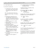
Page 16: ...e TCC in Figure 9 or Figure 12 for the ST time band setting in the AC PRO or AC PRO II 8 Verify that the trip unit saved the proper last trip data 9 Repeat for the other two phases if desired 4 9 Calculate Instantaneous I Pick Up Secondary Current Calculate Instantaneous secondary pick up current ISPU as follows For 1 Amp AC PRO or AC PRO II ISPU I Pick Up CT Primary Rating Example If the CT Prima...

Page 17: ...ar 8 button to reset the Timer 6 to zero 6 Push the Start 5 button An I trip should occur The test set current will stop and the Timer 6 will freeze displaying the trip time 7 Verify that the AC PRO or AC PRO II saved the proper last trip data 8 Repeat for the other two phases if desired 4 11 Calculate Ground Fault GF Pick Up Secondary Current Calculate the GF secondary pick up current GFSPU as fo...

Page 18: ... will freeze displaying the trip time 7 Verify that the trip unit saved the proper last trip data 4 13 Ground Fault GF Time Test To test the GF time delay trip 1 The first step is to select a test current For example 150 of the GF pick up The desired test current is then 1 5 X GFSPU Note to accurately test the GF delay the test current must be at least 110 of the GF pick up 2 Hold down the Current...

Page 19: ...ing is 1600 and the NOL Pick Up is 1600 amps then NOLSPU 1600 X 0 5 0 50 amp 1600 Note If the Neutral CT Secondary Rating is different than 1 0 or 0 5 use the 0 5 example above and replace 0 5 with the specific Neutral CT Secondary Rating 4 16 Neutral Overload NOL Pick Up Test AC PRO II only To test the NOL pick up 1 Temporarily turn Ground Fault protection OFF in the trip unit 2 Confirm the GF Sw...

Page 20: ...Fine 15 pots until the Current 12 display shows the test current calculated in step 1 Release the Current Preset 13 button 3 The GF Switch 10 should still be in the Ground Return GF position and the Phase selector 11 should still be set to GF 4 Push the Clear 8 button to reset the Timer 6 to zero 5 Push the Start 5 button and quickly make any minor adjustments required to the Amp Fine 15 pot The A...

Page 21: ...ack of Plug into MENU AC TRIP UNIT UTILITY RELAY COMPANY PICK UP SELF TEST OK ENTER QT DISPLAY QT Display jack Plug into Jack back of QT Display 2 Pole Plug into L P Q QUICK TRIP ON OFF with Quick Trip turned ON Red LED is ON N M Lockable Guard is not shown Note Quick Trip Switch Figure 7 AC PRO Quick Trip Testing Connections L AC PRO Trip Unit M AC PRO Test Set Harness N AC PRO Shielded Cable 8 C...

Page 22: ...y for use with AC PRO II trip unit Lockable Guard is not shown on back of Plug into QT Switch QUICK TRIP Plug into Jack R U with Quick Trip turned ON Red LED is ON T S DISPLAY AC PRO II Connector Plug into 24VDC Aux Power Connector AC PRO II Note Quick Trip Switch Figure 8 AC PRO II Quick Trip Testing Connections R AC PRO II Trip Unit S AC PRO II Test Set Harness T AC PRO II 4 C Quick Trip cable U...

Page 23: ...t when performing Quick Trip Instantaneous Tests 5 2 Quick Trip Instantaneous QT I Pick Up Test To test the QT I pick up 1 AC PRO Connect the Quick Trip Display P and the Quick Trip ON OFF Selector switch Q as shown in Figure 7 AC PRO II Connect the AC PRO II Quick Trip switch U as shown in Figure 8 2 Set the Quick Trip ON OFF Selector switch Q or U to ON 3 Hold down the Current Preset 13 while ad...

Page 24: ...d To test the QT GF pick up 1 AC PRO Connect the Quick Trip Display P and the Quick Trip ON OFF Selector switch Q as shown in Figure 7 AC PRO II Connect the AC PRO II Quick Trip switch U as shown in Figure 8 2 Set the Quick Trip ON OFF Selector switch Q or U to ON 3 Set the Phase Selector 11 switch to GF 4 Hold down the Current Preset 13 while adjusting the Amp Coarse 14 and Fine 15 pots to 90 of ...

Page 25: ...re are loose connections in the test cable 7 2 Thermal Limit As a protective feature the test set will stop delivering current and display a Thermal Limit message if high levels of test current remain for a prolonged time period The timeout for the thermal limit shutdown begins when any test current exceeds eight amps If a thermal limit occurs it must be cleared by pressing the Clear 8 button The ...

Page 26: ...AC PRO AC PRO II B 292 Secondary Injection Test Set Instruction Manual Rev 1 1 www utilityrelay com Page 23 This Page Intentionally Left Blank ...

Page 27: ... Up 20X 2X 01 150 1X I Pick Up 6X 4X 1200 10X 40sec 15sec 20sec 30sec 2 1 0 s I ST I T OFF 2 1 5 07sec T ON 0 7 s I T O N T O N 2 10sec 2 0 s SECONDS 1 10 4 0 s I 2 0 s I T O N 1 5 s I T O N T O N 2 2 3 0 s I T O N 2 2 SECONDS without I ST Delay with 2 T 1 1200 ST Pick Up 1 600 LT Pick Up 600 LT Pick Up 20X LT Delay 100 2 0 to 30 0 sec 0 5 sec steps 3 0 s 2X 1000 1X 6X 4X 10X 1 1 0 5A steps for CT...

Page 28: ...AC PRO AC PRO II B 292 Secondary Injection Test Set Instruction Manual Rev 1 1 www utilityrelay com Page 25 Figure 10 AC PRO Unbalance TCC Ground Fault TCC ...

Page 29: ...ples of Long Time Pick Up 20X 2X 01 150 1X QT I Pick Up 6X 4X 1200 10X 1 5 1 5 Quick Trip Instantaneous Time Current Curve Quick Trip Instantaneous 150 to 1200 of SECONDS 1A steps for CTs 225A 100A steps for CTs 5000A 10A steps for CTs 225A 1000A steps for CTs 5000A 1 Phase power up time Allowance for Instantaneous I Pick Up Minimum possible Quick Trip Instantaneous QT I Pick Up Allowance for 3 Ph...

Page 30: ...sec 30sec 2 1 0 s I ST I T OFF 2 1 5 07sec T ON 0 7 s I T O N T O N 2 10sec 2 0 s SECONDS 1 10 4 0 s I 2 0 s I T O N 1 5 s I T O N T O N 2 2 3 0 s I T O N 2 2 1 5 SECONDS without I ST Delay with 2 T 1 1200 ST Pick Up 10 600 LT Pick Up 600 LT Pick Up 20X LT Delay 100 2 0 to 30 0 sec 0 5 sec steps 3 0 s 2X 1000 1X 6X 4X 10X 100 1000 AC PRO II O L Rev 1 01 01 15 2015 0 5A steps for CTs 225A 10A steps...

Page 31: ...teps 100 20 40 Pick Up 200 1A steps for CTs 225A 60 SECONDS 1000 20sec without I 30sec with 1 GF Delay 5 1 4 0 s 10 2 0 s 100 3 0 s 5 0 s 40sec 50sec T 2 Pick Up 200 GF 50sec AC PRO II G F Rev 1 02 05 12 2015 CT Secondary Rating 0 5A and above 1200A Max 50 to 200 of CT Rating CT Secondary Rating below 0 5A 1200A only CT ratios over 24000 requires VDM or 24VDC at 12xCT GF ends does not comply with ...

Page 32: ...p QT I Pick Up QT I Pick Up LT Pick Up 100A steps Current in Multiples of Long Time Pick Up 20X 2X 01 150 1X QT I Pick Up 6X 4X 1200 10X 1 5 1 5 Quick Trip Instantaneous Time Current Curve Quick Trip Instantaneous 150 to 1200 of SECONDS 1A steps for CTs 225A 10A steps for CTs 225A 4X 1X 2X 10X 6X 20X R R R R AC PRO II Q T Rev 1 02 01 15 2015 CT Secondary Rating 0 5A and above 1200A max 50 to 200 o...

Page 33: ...0 sec 0 5 sec steps 3 0 s 1000 Current in Percent of NOL Pick Up 100 200 500 1000 Pick Up Neutral Overload NOL Pick up 5A steps for CTs 225A 0 5A steps for CTs 225A Neutral CT Secondary Rating 0 5A and above 20 to 200 of CT Rating Neutral CTs Secondary Rating below 0 5A 50 to 200 of CT Rating AC PRO II NOL Rev 1 2 07 14 2015 NOL ends at 1200 of CT Rating Figure 15 AC PRO II Neutral Overload TCC ...

Page 34: ...T P I L B ...

Page 35: ...T P I L B ...

Page 36: ...C h a g r i nF a l l s O H 4 4 0 2 3 P h o n e 8 8 8 2 8 9 2 8 6 4 www u t i l i t y r e l a y c o m I A C 2 P R O T S I A C 2 P R O T S ...

Reviews: