AC-PRO
®
& AC-PRO-II
®
B-292 Secondary Injection Test Set Instruction Manual Rev 1.1
www.utilityrelay.com
Page 5
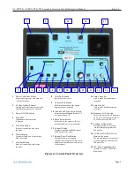
1
Power Cable/Fuse Holder
Power cable connector with main fuse.
(120Vac 50/60Hz).
2
Cooling Airflow Exhaust
Cooling air for the test set exits via this
filter opening (must not be blocked).
3
Power ON/OFF Switch
4
Start LED
Illuminates when test current
is flowing.
5
Start Push Button
Starts test current flow and starts
the timer.
6
Timer Display
Displays elapsed time of test current
flow in seconds.
7
Stop Push Button
Stops test current flow and freezes
the timer.
8
Clear Push Button
Resets the timer to zero.
9
Contrast Push Button
Hold this button in until the desired
display contrast is reached.
10
Ground Fault Type Select Switch
Selects between Standard Residual GF
or Ground Return GF.
11
Phase Select Switch
Selects one of the phases (A,B,C) or
ground fault as the test current path.
12
Current Display
Displays measured true RMS current
and Current Preset
value.
13
Current Preset Push Button
When held, the current display
indicates the setting of the Amp Coarse
and Fine pots but does not send current
to the trip unit.
14
Amp Coarse Pot
Used to make large adjustments
in current.
15
Amp Fine Pot
Used to make small adjustments
in current.
16
Frequency Select Switch
This switch selects the AC frequency;
25, 40, 50 or 60 Hertz for AC-PRO.
50 or 60 Hertz for AC-PRO-II.
17
Cooling Airflow Intake
Cooing air for the test set enters
via this filter opening (must not
be blocked).
18
AC-PRO or AC-PRO-II Test
Harness Connector
The trip unit connects to the test-set
with the supplied wire harness via
this connector.
19
24V Fuse / Fuseholder (fuse
is rated 1A/250V, 3AG slow
blow fuse)
Figure 4: Control Panel Overview
2
1
13
14
16
18
17
8
11
9
7
15
4
3
5
12
6
10
19

