AC-PRO
®
& AC-PRO-II
®
B-292 Secondary Injection Test Set Instruction Manual Rev 1.1
www.utilityrelay.com
Page 11
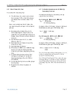
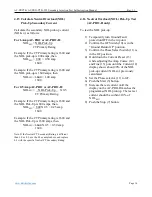
Example: If the CT Primary rating is 1600 and
the LT Pick-Up is 1600 amps, then
LT
SPU
= 1600 X 0.5 = 0.50 amp
1600
Note: If CT Secondary Rating is different than 1.0 or 0.5,
use the 0.5 example above and replace 0.5 with the
specific CT Secondary Rating.
Note: If Phase CT and Neutral CT do not have the same
Secondary Rating (i.e. if both not 1-Amp), temporarily
turn off Ground Fault Protection in the Trip Unit when
performing Long Time, Short Time, and Instantaneous
Tests.
4.4
Long Time (LT) Pick-Up Test
To test the LT pick-up:
1)
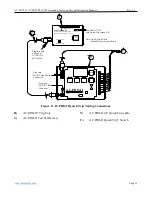
Hold down the Current Preset (13)
while adjusting the Amp Coarse (14)
and Fine (15) pots until the Current (12)
display shows about 90% of the LT
pick-up current (LT
SPU
) previously
calculated.
2)
Set the Phase selector (11) to either
Phase A, B or C.
3)
Push the Start (5) button.
4)
Increase the test current until the
display on the AC-PRO or AC-PRO-II
matches the programmed LT pick-up.
The red pick-up LED on the AC-PRO
or AC-PRO-II should be flickering or
solidly on. The test set current should
be within
±
10% of LT
SPU
.
5)
Push the Stop (7) button.
6)
If desired, test the other two phases in
the same way.
4.5
Long Time (LT) Time Test
To test the LT time delay trip:
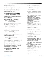
1)
The first step is to select a test current.
For example, three times the LT pick-up
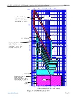
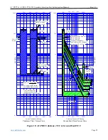
(3X on the TCC in Figure 9 or Figure
12). The desired test current is then 3 X
LT
SPU
.
Note, to accurately test the LT delay, the
test current must be at least 110% of the LT
pick-up.
2)
Hold down the Current Preset (13)
while adjusting the Amp Coarse (14)
and Fine (15) pots until the Current (12)
display shows the test current calculated
in step 1. Release the Current Preset
(13) button.
3)
Set the Phase selector (11) to either
Phase A, B or C.
4)
Push the Clear (8) button to reset the
Timer (6) to zero.
5)
Push the Start (5) button and quickly
make any minor adjustments required to
the Amp Fine (15) pot. The red pick-up
LED should be on. AC-PRO should
display “OVERLOAD”. AC-PRO-II
should display the current value.
6)
When the trip unit trips, the test set
current will stop and the Timer (6) will
freeze and display the total trip time.
7)
Compare the trip time with the TCC in
Figure 9 or Figure 12 for the LT time
band setting in the AC-PRO or
AC-PRO-II. The trip time can also be
verified against the LT Test Chart on
the inside panel of the test set case. The
LT Test Chart is also available at:
http://www.utilityrelay.com/PDFs/Prod
uct%20Manuals/AC-PRO_&_AC-
PRO-II_LT_Trip_Times.pdf
Verify that the trip unit saved the proper
last trip data.
8)
Repeat for the other two phases if
desired.

