background image


3


1. Brief introduction                                                                             


1.2


Description of commonly used symbols 


The following symbols will be used in this manual and may appear during 
the course of your practical applications. Therefore, all users should be 
familiar with them and understand their meanings. 


1.3 Appearance 


Notation and Explanation 

Notation 

Explanation Notation 

Explanation 


Alert you to pay special 

attention 


Protective ground 


Caution of high voltage 


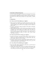
Alarm silence 


Turn on the UPS 


Overload indication 


Turn off the UPS 


Battery check 


Idle or shut down the UPS 


Recyclable 

  Alternating current source (AC) 


Do not dispose with 

ordinary trash 


Direct current source (DC) 


Battery 

Summary of Contents for Queen Star Series

Page 1: ...USERMANUAL Queen StarSeriesOnline UPS 6K 20KVA ...

Page 2: ...backup time model UPS with the external battery 10 11 3 4 Parallel operation 11 14 4 Operation and Operating mode 15 22 4 1 Operation 15 16 4 2 Operating mode 16 22 5 Battery maintenance 23 6 Notes for battery disposal and battery replacement 24 7 Troubleshooting 25 26 Appendix 1 Description of Display panel 27 28 Appendix2 Indicator and alarm 29 30 8 Chapter Operation LCD model 31 42 8 1 Operatio...

Page 3: ... with the proven on line double conversion architecture this series of UPS offers the greatest degree of availability in power protection and provides continuous high quality AC power to connect strict load especially for the basic equipments in some areas as finance communication government traffic manufacture education and so on This manual is applicable to the following models Type Model Input ...

Page 4: ...r with them and understand their meanings 1 3 Appearance Notation and Explanation Notation Explanation Notation Explanation Alert you to pay special attention Protective ground Caution of high voltage Alarm silence Turn on the UPS Overload indication Turn off the UPS Battery check Idle or shut down the UPS Recyclable Alternating current source AC Do not dispose with ordinary trash Direct current s...

Page 5: ...4 BACK VIEW OF 6K 1 Brief introduction BACK VIEW OF 6KL BACK VIEW OF 10K ...

Page 6: ...5 1 Brief introduction BACK VIEW OF 10KL BACK VIEW OF 31 10KL ...

Page 7: ...KL 50 120 274 32Amax 220VAC 27A 533x260x501 21 10KVA 8KW 10K 50 120 274 50Amax 220VAC 45A 560x260x717 67 5 10KVA 8KW 10KL 50 120 274 50Amax 220VAC 45A 533x260x501 23 10KVA 8KW 31 10KL 50 120 274 50Amax 220VAC 45A 533x260x501 24 12KVA 9 6KW 31 12KL 50 120 274 80Amax 220VAC 54A 560x260x717 39 5 15KVA 12KW 31 15KL 50 120 274 80Amax 220VAC 68A 560x260x717 39 5 20KVA 16KW 31 20KL 50 120 274 100Amax 220...

Page 8: ...mode 1 Synchronized 46 54Hz 2 50Hz Line 40 46 and 54 60Hz Battery mode 50Hz THD 2 Full load Linear load 105 125 load transfers to bypass mode after 1 minutes 125 135 load transfers to bypass mode after 30second 3 1 maximum Operating environment Temperature Humidity Altitude Storage temperature 0 40 95 1000m 0 40 Note If the UPS is installed or used in a place where the altitude is above than 1000m...

Page 9: ...nsufficient capacity Do not let battery or batteries get close to any heating source and do not incinerate battery or batteries they may explode Do not open or mutilate the battery or batteries released electrolyte is highly poisonous and harmful to the skin and eyes Do not short the positive and negative of battery electrode Otherwise it may cause electric shock or fire To avoid the risk of being...

Page 10: ...ot be blocked so as to ensure good ventilation Allow at least 0 5m of space on each side 3 In case if the UPS is unpacked installed and used at very low temperatures condensation of water drops may appear It is necessary to wait until the UPS is fully dried inside out before proceeding to installation and use Otherwise there may be a risk of electric shock 3 2 2 Installation Installation and wirin...

Page 11: ...ch consumes electro equipment and the ground wire The wire diameter of protective earth ground wire should be at least as above mentioned for each model and green wire or green wire with yellow ribbon wire is used 7 After having completed the installation make sure the wiring is correct 8 Please install the leak current protective breaker at the output power distribution panel of the UPS if necess...

Page 12: ...15KL 31 20KL 3 3 Operating procedure for connecting the long backup time model UPS with the external battery 3 3 1 The nominal DC voltage of external battery pack is 192VDC Each battery pack consists of 16 pieces of 12V maintenance free batteries in series To achieve longer backup time it is possible to connect multi battery packs but the principle of same voltage same type should be strictly foll...

Page 13: ...pack in the ON position After that set the input breaker in the ON position The UPS begins to charge the battery packs at the time 3 4 Parallel operation 3 4 1 Brief introduction of the redundancy N X is currently the most reliable power supply structure N represents the minimum UPS number that the total load needs X represents the redundant UPS number i e the fault UPS number that the system can ...

Page 14: ...reaker panel is less than 20 meters the difference between the wires of input output of the UPSs is required to be less than 20 When the distance between the UPSs in parallel and the breaker panel is greater than 20 meters the difference between the wires of input output of the UPSs is required to be less than 10 3 4 3 Operation and maintenance 1 To perform the general operation follow the stand a...

Page 15: ...14 3 Installation ...

Page 16: ...15 3 Installation ...

Page 17: ...ng order A few seconds later the INV LED is turned on the UPS is already running in Utility Power mode If the utility power is abnormal the UPS will operate in battery mode without output interruption of the UPS 4 1 2 Turn on the UPS with no utility power supplied 1 Press the ON button continuously for more than 1 second to power on the UPS For long back up time model L model please make sure that...

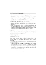
Page 18: ...play panel and no voltage is available from the UPS output Suggestions Please turn off the connected loads before turning on the UPS and turn on the loads one by one after the UPS is working in INV mode Turn off all of the connected loads before turning off the UPS 4 2 Operating mode 4 2 1 Normal power mode In the normal mode the display on the front panel is shown in the following diagram The uti...

Page 19: ... confirmed without any problem it may be due to the defect or aging of the battery please refer to the troubleshooting in chapter 7 to solve the problem accordingly Note Connection to the power generator should be made according to the following steps Activate the power generator and wait until the operation is stable before connecting the output of the power generator to the UPS be sure that the ...

Page 20: ...hen the battery capacity decreases the number of load battery capacity indicators turned on will decrease If the battery voltage drops to the pre alarm level capable of maintaining the backup time for more than 2 minutes the alarm will beep every second to remind the user of insufficient battery capacity 4 2 3 Bypass mode When operating in bypass mode set up through UPSilon software the display on...

Page 21: ...when the UPS is in use it shows that the UPS is operating in abnormal mode Please refer to the troubleshooting in section 7 for details 4 2 5 Setting the output voltage and frequency 1 Connect the mains input to the UPS and make the UPS works in standby mode or bypass mode 2 Press the F and OFF button more than one second then release the buzzer will beep once and the bypass indicator with battery...

Page 22: ...ing but before the setting please confirm the frequency setting is enabled the inverter indicator blink if not press ON key about one second in order to switch to the frequency setting screen 8 When done Press the F and OFF button more than one second then release the buzzer will beep once exit the setting mode In the setting process if no key is detected within twenty second the UPS exits the set...

Page 23: ...r other optional card to achieve remote management of the UPS Please contact your local distributor for further information 4 2 8 Description of communication interface 1 The standard RS232 port is applicable to communicate with computer Description and pin assignment of RS232 Baud rate 2400bps Data bit 8 bit Ending bit 1bit Parity bit None DB 9 pin assignment RS232 Interface ...

Page 24: ...s to monitor and manage the UPS through installed the AS400 card optional PIN1 UPS failure normally open active close PIN2 Summary alarm PIN3 Ground PIN4 Remote shutdown PIN5 Common PIN6 Bypass active relay close PIN7 Low battery PIN8 UPS on relay close PIN9 Utility Power failure normally open active close AS400 Interface ...

Page 25: ...rged and discharged every 2 months The standard charging time should be at least 12 hours Under normal conditions the battery life lasts 3 to 5 years In case if the battery is found not in good condition earlier replacement should be made Battery replace event should be performed by qualified personnel Replace batteries with the same number and same type of batteries Keep the ambient temperature b...

Page 26: ...ery otherwise it may result in electric shock or fire 6 Make sure that there is no voltage before touching the batteries The battery circuit is not isolated from the input potential circuit There may be hazardous voltage between the battery terminals and the ground 7 Even though the input breaker is disconnected the components inside the UPS are still connected with the batteries and there are pot...

Page 27: ...ts down due to its internal fault Please contact the distributor or service center The 1 Fault LED and the 5 LED are turned on the UPS beeps continuously The UPS shuts down due to its internal fault Please contact the distributor or service center The utility power LED flashes The voltage or frequency of the utility power is out of the input range of the UPS The UPS is running in battery mode To s...

Page 28: ...l equipment Battery aged Replace the batteries Please contact the distributor to obtain the parts and replacement service The UPS cannot power on after pressing the ON button The ON button is pressed too briefly Press the ON button for more than 1 second The UPS is not connected to the battery or the battery pack voltage is too low Check the battery or recharge the battery UPS internal fault Pleas...

Page 29: ...s buzzer beeps twice can start the battery self diagnosis 2 Silence function in battery bypass mode In battery bypass mode when the buzzer beeps pressing and holding the function button for more than 5 seconds buzzer beeps one times can silence the buzzer Press the button for more than 5 seconds buzzer beeps twice again to resume the alarm function Note The alarm silencing function of the Function...

Page 30: ...ttery capacity indicator 4 Green Load battery capacity indicator 5 Green Load battery capacity indicator 6 Green Load battery capacity indicator 7 Orange Bypass indicator When the indicator on it shows that the loading current is supplied from the utility power directly 8 Green Utility power indicator When the indicator on it shows that the utility power is normal 9 Green Inverter indicator When t...

Page 31: ...ry capacity Beep once every 4 sec 9 61 80 Battery capacity Beep once every 4 sec 10 81 100 Battery capacity Beep once every 4 sec 11 Bypass mode Beep once every 2 min 12 Overloaded in Normal mode Beep twice every sec 13 Overloaded in bypass mode Beep twice every sec 14 Utility power abnormal None 15 Bypass mode abnormal None 16 Overload in Battery mode pre alarm Beep twice every sec 17 Overload fa...

Page 32: ... 28 Over Charger Sustained beep 29 Reversed polarity L N of input wiring or disconnected with ground Beep once every sec 30 BAT fault Sustained beep 31 EPO mode Beep once every sec 32 Bus short Sustained beep 33 Negtive power fault Sustained beep 34 React Power Fault Sustained beep 35 Power Fault Sustained beep 36 Inv Rly Stick Fault Sustained beep 37 Inv Rly Open Fault Sustained beep 38 Line SCR ...

Page 33: ... beeps twice can start the battery self diagnosis b Silence function in battery bypass mode In battery bypass mode when the buzzer beeps pressing and holding the function button for more than 5 seconds buzzer beeps two times can silence the buzzer Press the button for more than 5 seconds buzzer beeps twice again to resume the alarm function c LCD display screen switch Pressing the function button ...

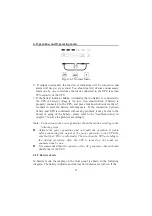
Page 34: ...2 1 Normal mode When operating in the normal mode the display of main page on the front panel is shown as the figure 8 2 The utility power indicator and the Inverter indicator are turn on Load information area shows load value and the battery level area indicates dynamically when the battery is not full charged the battery level icons lit one after another circularly When the battery is full charg...

Page 35: ...e Note Connection to the power generator should be made according to the following steps Activate the power generator and wait until the operation is stable before connecting the output of the power generator to the UPS be sure that the UPS is in idle mode Then turn on the UPS according to the startup procedure After the UPS is turned on the loads are connected one by one It recommended that the c...

Page 36: ...nd the bypass indicator are turn on The load battery capacity indicator will be turned on in accordance with the load capacity connected Load information area shows load value and the battery level area indicates dynamically when the battery is not full charged the battery level icons lit one after another circularly When the battery is full charged all the level icons are turn on 1 When operating...

Page 37: ...ower used by the load is directly from the utility power via internal EMI filter Figure 8 4 Bypass Mode 8 2 4 LCD indication of UPS alarm status and faults In the event of an UPS fault UPS enters fault operation mode at this point the fault icon turn on consistently the buzzer beeps continuously and the data information area shows current fault code refer to table 8 5 1 the display on the front pa...

Page 38: ...uate battery autonomy 1 Turning on the UPS The operation of turning on the UPS contains turning on with utility power and turning on without utility power 1 Turning on with utility power Connect the mains input to the UPS press the ON button more than one second UPS start to turn on At this point the LCD begins to conduct self diagnosis all the LCD indicators are turn on about 4 seconds Seconds la...

Page 39: ...n the front panel and no output is available from the UPS outlets system completely power down 2 Completely power down the UPS from Battery mode Press the OFF button persistently for more than 1 second to power off the UPS When being powered off the LCD will start self diagnosis all the LCD indicators are turn on about 4 seconds seconds later not any display is shown on the front panel and no volt...

Page 40: ... processes stated above check that the LED indication of the UPS agrees with the UPS operation mode 8 5 Setting the output voltage and frequency 1 Connect the mains input to the UPS and make the UPS works in standby mode or bypass mode 2 Press the F and OFF button more than one second then release the buzzer will beep once the OUTPUT is flashing which means all of bottom are used for UPS setting a...

Page 41: ...fault still persists please contact our customer service center Faults Possible cause Solution Fault Warning code Fault icon Alarm F01 On constantly Beep continuously Bus soft start fails Please contact the distributor or Service center F02 On constantly Beep continuously BUS over voltage fault Please contact the distributor or Service center F03 On constantly Beep continuously BUS low voltage fau...

Page 42: ... center F25 On constantly Beep continuously INV Rly stick fault Please contact the distributor or Service center F26 On constantly Beep continuously Line input SCR fault Please contact the distributor or Service center F32 On constantly Beep continuously Parallel line loss Please check parallel line connect or not F34 On constantly Beep continuously CAN parallel line loss Please contact the distri...

Page 43: ...nnected to the UPS A15 Blink once every second Beep two sounds every second Overload fault Reduce the member of loads connected to the UPS A16 Blink once every second Beep one sound every second Fan failure Ensure that the fan is not locked A18 Blink once every second Beep one sound every second Charger fail Please contact the distributor or Service center A20 Blink once every second Beep 3 sounds...

Page 44: ...ollowing information Model No and Serial No of the UPS The date when the problem arose Complete description of the problem including the panel display alarm warning and power condition and the load capacity If the UPS is a long backup time model you may also provide the battery information ...

Reviews: