12
QUICK START
5 - Reinstall the print drum on the Hub Assembly and re-
place the Print Drum Retaining Knob.
FIGURE 20
FIGURE 21
4 - When using the smaller individual characters to make up a
code message, use the Type Blocking Kit included with your
coder to support the leading and trailing ends of the type
as shown.
Characters with only a 2 or 3 rib backing do not have the stabil-
ity of the larger sizes when snapped into the drum cover. Add-
ing the rib backed type blocks on either side of the code will
provide added stability. The Type Blocks are not as thick as the
Type and will not pick up ink from the Transfer Roll.
The print drums on indexing coders always return to the same rotational or “indexed” position after every print is
applied and the print drum is lifted off the surface of the material being printed. In order to ensure that fresh ink is
applied to the die faces on every printing cycle, the dies should be positioned rotationally upstream of the Transfer
Roll when the print drum is in the indexed position.
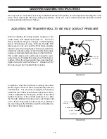
ADJUSTING THE DIE POSITION ON INDEXING PRINTERS
1 - To position the printing dies, slightly loosen the Print
Drum Knurled Nut. Rotate the Print Drum as neces-
sary to bring the leading edge of the die into the posi-
tion indicated and then hold the Print Drum stationary
while tightening the Print Drum Knurled Nut to lock
the Print Drum in place.
FIGURE 22
When the printer is used with the leading edge of the printing
die positioned as shown, the printing dies are immediately ro-
tated past the anilox roll where the ink is applied and then the
impression is immediately transferred to the surface of the
material being printed.
PRINT DRUM ROTATION
KNURLED NUT
DIE LOCATION
LEADING EDGE OF
DIE HERE
TRANSFER ROLL
Summary of Contents for HPNP-100
Page 25: ...25 ...


