background image

Assembling Your ILS System

15

Laser Cartridge Installation

Note:

  The following images illustrate a ILS12.150D laser system with two laser cartridges.  If you own a 

single laser cartridge system, you will install the single laser cartridge only.

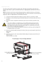
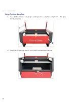
Make sure that your power cord to the system is not plugged in at this time.  Place your finger 

1. 

on the button part of the latch until the latch is released.  Gently fold back the rear cover.  Some 
laser systems are shipped with keyed locks. 
 

Note:

  Access latches for the laser cover are lockable.  However, all systems are shipped from 

the factory with latches unlocked.  If you need to lock the latches, please contact our Customer 
Service at 480-609-0297 (USA), +43 1 402 22 50 (Austria), +81 (45) 224-2270 (Japan) or e-mail us 
at [email protected] for keys.

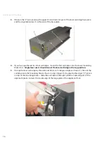
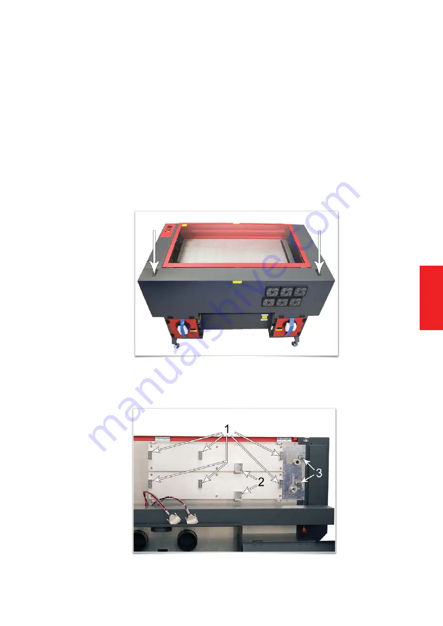
Visually locate the mounting blocks (1), the laser latch(es) (2) and alignment fork(s) (3).  Notice 

2. 

that the alignment fork has two plates, one small and one large.  Locate the gap between the 
two plates.

Summary of Contents for Industrial ILS12.150D

Page 1: ...www ulsinc com Installation Set up Guide ILS9 75 ILS9 150D ILS12 75 ILS12 150D...

Page 2: ......

Page 3: ...tion CD ROM 11 Assembling Your ILS System System Unpacking ILS9 75 ILS9 150D ILS12 75 and ILS12 150D 13 Laser Cartridge Installation 15 Laser System Leveling 18 Finalizing the Connections 24 Checking...

Page 4: ...1988 Universal Laser Systems has been committed to continually improving our technology and customer driven laser solutions Your satisfaction is very important to us and we welcome your feedback Tell...

Page 5: ...81 45 224 2270 Japan or e mail us at support ulsinc com Please refer to the Safety Manual before operating your laser system Environment User Supplied The laser system must be installed in an office...

Page 6: ...the user Exhaust System User Supplied We recommend you consult with a licensed contractor to meet local safety and building code 1 requirements The exhaust system must be capable of supplying a minimu...

Page 7: ...ermining the correct exhaust blower unit Installing an undersized or oversized blower is not only unsafe but can also lead to excessive wear and tear to the laser system and premature failure ILS9 75...

Page 8: ......

Page 9: ...imum t VGA monitor minimum 1024 x 768 resolution t CD ROM drive burner t Mouse and keyboard t Available USB 2 0 Hi Speed compliant port only t Computer speakers optional t 600 DPI scanner optional t I...

Page 10: ...ettings link In the Performance section click Settings then click Adjust For Best Performance and then click Apply Computer Power Management Power management is a configuration setting in Windows XP a...

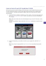
Page 11: ...ide Insert the Software Installation CD ROM into your PC s CD drive It should automatically launch 1 the Universal Control Panel Installation window Select the laser series you are installing on the c...

Page 12: ...er s processor speed When the installation process is finished the 5 Completing the ULS Software Setup Wizard window will appear Read the instructions and make your desired selection If you Reboot Now...

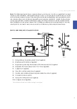
Page 13: ...king Beam Alignment CAUTION Do not attempt to move or lift this system alone Obtain assistance from three or four ad ditional people when lifting or carrying secure motion system and doors before lift...

Page 14: ...ped around the laser system once it has been removed from the 3 crate If you have a forklift you can lift the laser system off of the pallet by inserting the forks a spread as wide apart as possible u...

Page 15: ...is released Gently fold back the rear cover Some laser systems are shipped with keyed locks Note Access latches for the laser cover are lockable However all systems are shipped from the factory with l...

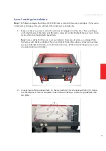
Page 16: ...r mounting 4 blocks first Single laser users should mount the laser cartridge in the top position Pick up the laser cartridge by the ends and tilt it at a 30 degree angle as shown 1 Mount the 5 cartri...

Page 17: ...binding laser latch Once installed verify that the alignment plate is centered within the alignment fork Plug in the power connector 1 to the corresponding laser cartridge The power connector is 7 la...

Page 18: ...p Guide 18 Laser System Leveling Once the laser system is in its proper operating location open the top door first 1 then open 1 the front door 2 Locate the small bubble level 1 on the front of the la...

Page 19: ...stment screw 2 until the front of the laser system is 3 level from one side to the other Once the front of the system is level secure the front casters by tightening the nut 1 up against the cart leg...

Page 20: ...is 5 level from one side to the other Once the back of the system is level secure the back casters by tightening the nut 1 up against the cart leg Located within the body of the laser system underneat...

Page 21: ...move all of the foam pieces that hold the X Axis Arm in place Three pieces are located on 7 each end of the X Axis Arm 1 and one holds the Focus Carriage in place 2 Manually move the Focus Carriage by...

Page 22: ...like the diagram to the right in the upper left corner of the system This corner will be your reference point Using the upper left corner as a reference point move the focus carriage by hand to each 1...

Page 23: ...eight tighten the lock nut 1 When you are done the focus tool fit at all four corners should be the same Once properly leveled 12 proceed to page 24 Alternate leveling method For the best leveling res...

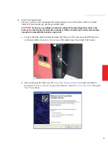
Page 24: ...to plug it into their power source CAUTION Make sure that you attach the adapter correctly to the power cord and that your power source is properly grounded earthed Do not power on the laser system at...

Page 25: ...ther devices between the computer s USB port and the port on the laser system sporadic or unpredictable behavior may result Connect the USB cable provided between the USB port of the computer and the...

Page 26: ...ue Anyway Do not be concerned Installing the ULS Firmware will not harm your computer in any way The firmware will begin to load Click e Finish to close the Wizard Another set of f New Hardware Wizard...

Page 27: ...ing on the Universal Control Panel icon on your desktop Power on the laser system by pressing the Power switch 4 on the ILS system keypad With the top door open a red dot will appear on the masking ta...

Page 28: ......

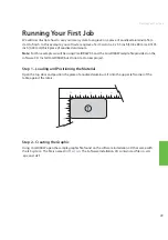
Page 29: ...using CorelDRAW X3 and the CorelDRAW sample file provided on the software CD Install CorelDRAW but do not start a new project Step 1 Loading and Positioning the Material Open the top door and positio...

Page 30: ...e metal and 3 then select the correct material type Aluminum Anodized Figure 5 Set the Fixture Type to NONE 4 Note If you were using an optional accessory or custom fixture you would choose it from th...

Page 31: ...rect check focus manually as described in the User Manual located in the Reference Guide packet and adjust if necessary If you cannot resolve the issue please contact your distributor or the ULS Custo...

Page 32: ...Notes...

Page 33: ...Notes...

Page 34: ...rademarks or registered trademarks of their respective companies Universal s laser systems are protected under one or more of U S Patents 5 051 558 5 661 746 5 754 575 5 867 517 5 881 087 5 894 493 5...

Page 35: ......

Page 36: ...www ulsinc com 050 3250 00 A REV0409...

Reviews: