WELD SENTRY 2
Page 11
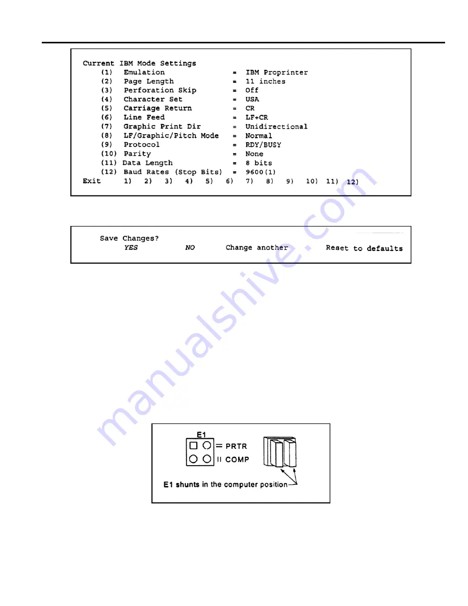
a) Move the printhead beneath "Exit". Press "Font" to Enter. The following will be
displayed:
g) Select YES to save changes.
COMMUNICATIONS CONFIGURATION
The Weld Sentry's RS232 communication port (transmit, send and busy lines) is configured for use with the
Kodak printer and many IBM compatible computers. Other types of serial printers or computers may
require a different configuration.
CHANGE RS232 PIN ASSIGNMENTS
1. Disconnect the Sentry's line cord from the power line. Remove the cover.
2. Locate the weld monitor module PCB at the right side of the unit.
3. Refer to Section 4 - Specification and Drawing 4-32603 - Weld Monitor Module.
4. Determine the communications configuration for your printer or computer.
5. Select the corresponding Weld Sentry shunt configurations.
6. Place the two E1 shunts parallel to one another as shown in Figure 7.
Figure 7 - Move E1 Shunt to select printer or computer
7. Move the shunts on E2 to E5 to the appropriate top or bottom position.
8. Program the Weld Sentry for communication configurations, select Main Menu/System
Menu/Communications.
CONTROL SIGNALS
Summary of Contents for WELD SENTRY 2
Page 5: ......


