


11
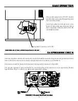
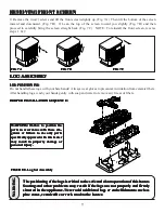
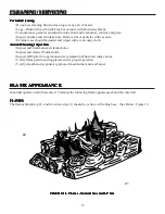
1) Remove the two(2) screws and lift the front screen slightly up. (Fig. 7A) Then tilt the bottom of the screen
inward and downward. (Fig. 7B) 2) Lean the top of the screen toward you slightly (Fig. 7B) and then
proceed to carefully bring the screen straight back (Fig. 7C). NOTE: To reinstall the front screen, reverse
steps 1 & 2.
REMOVING FRONT SCREEN
REMOVING FRONT SCREEN
REMOVING FRONT SCREEN
REMOVING FRONT SCREEN
REMOVING FRONT SCREEN
WWWWW
ARNINGARNINGARNINGARNINGARNING
T
T
T
T
The positioning of the lo
he positioning of the lo
he positioning of the lo
he positioning of the lo
he positioning of the logs is cr
gs is cr
gs is cr
gs is cr
gs is critical to the saf
itical to the saf
itical to the saf
itical to the saf
itical to the safe and c
e and c
e and c
e and c
e and clean oper
lean oper
lean oper
lean oper
lean opera
a
a
a
ation of this hea
tion of this hea
tion of this hea
tion of this hea
tion of this heater
ter
ter
ter
ter.....
Sooting and other pr
Sooting and other pr
Sooting and other pr
Sooting and other pr
Sooting and other prob
ob
ob
ob
oblems ma
lems ma
lems ma
lems ma
lems may r
y r
y r
y r
y result if the lo
esult if the lo
esult if the lo
esult if the lo
esult if the logs ar
gs ar
gs ar
gs ar
gs are not pr
e not pr
e not pr
e not pr
e not proper
oper
oper
oper
operllllly and f
y and f
y and f
y and f
y and fir
ir
ir
ir
irml
ml
ml
ml
mly
y
y
y
y
situated in the appliance. Never add additional logs or embellishments such as
situated in the appliance. Never add additional logs or embellishments such as
situated in the appliance. Never add additional logs or embellishments such as
situated in the appliance. Never add additional logs or embellishments such as
situated in the appliance. Never add additional logs or embellishments such as
pine cones,
pine cones,
pine cones,
pine cones,
pine cones, v
v
v
v
ver
er
er
er
ermiculite or r
miculite or r
miculite or r
miculite or r
miculite or roc
oc
oc
oc
ock w
k w
k w
k w
k wool to the hea
ool to the hea
ool to the hea
ool to the hea
ool to the heater
ter
ter
ter
ter.....
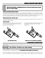
LOG POSITIONING
LOG POSITIONING
LOG POSITIONING
LOG POSITIONING
LOG POSITIONING
Do not handle these logs with your bare hands! Always wear gloves to prevent skin irritation from ceramic fibers.
After handling logs, wash your hands gently with soap and water to remove any traces of fibers.
PROPER INSTALLATION SEQUENCE:
PROPER INSTALLATION SEQUENCE:
PROPER INSTALLATION SEQUENCE:
PROPER INSTALLATION SEQUENCE:
PROPER INSTALLATION SEQUENCE:
LOG
LOG
LOG
LOG
LOG ASSEMBL
ASSEMBL
ASSEMBL
ASSEMBL
ASSEMBLY
Y
Y
Y
Y
FIG 7C
FIG 7C
FIG 7C
FIG 7C
FIG 7C
FIG 7B
FIG 7B
FIG 7B
FIG 7B
FIG 7B
FIG 7A
FIG 7A
FIG 7A
FIG 7A
FIG 7A
FIGURE 8. Log Set Assembly
FIGURE 8. Log Set Assembly
FIGURE 8. Log Set Assembly
FIGURE 8. Log Set Assembly
FIGURE 8. Log Set Assembly
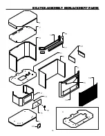
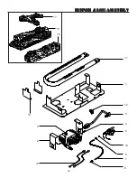
WARNING: Failure to position the
WARNING: Failure to position the
WARNING: Failure to position the
WARNING: Failure to position the
WARNING: Failure to position the
parts in accordance with these dia-
parts in accordance with these dia-
parts in accordance with these dia-
parts in accordance with these dia-
parts in accordance with these dia-
grams or failure to use only parts
grams or failure to use only parts
grams or failure to use only parts
grams or failure to use only parts
grams or failure to use only parts
specifically approved with this heater
specifically approved with this heater
specifically approved with this heater
specifically approved with this heater
specifically approved with this heater
may result in property damage or
may result in property damage or
may result in property damage or
may result in property damage or
may result in property damage or
personal injury.
personal injury.
personal injury.
personal injury.
personal injury.


