background image

7

INST

INST

INST

INST

INSTALLA

ALLA

ALLA

ALLA

ALLATION

TION

TION

TION

TION

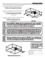
The following formula can be used to determine the maximum
heater rating per the definition of unconfined space:

BTU/HR = (L1+L2) Ft x (W) Ft x (H) Ft x 1000

50

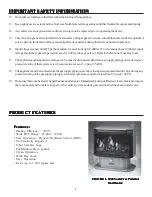
Consider two connecting rooms with an open area between,
with the following dimensions:(See Fig. 2, Example)

L1=15-1/2 Ft., L2=12 Ft., W=12 ft., H=8Ft

50

=52800 BTU/HR

If there were a door between the two rooms the calculation
would be based only on the room with the heater.

BTU/HR=(15-1/2) x (12) x (8) x 1000

50

=29760 BTU/HR

FIGURE 2.

FIGURE 2.

FIGURE 2.

FIGURE 2.

FIGURE 2.

W

W

W

W

When installing the a

hen installing the a

hen installing the a

hen installing the a

hen installing the appliance dir

ppliance dir

ppliance dir

ppliance dir

ppliance directl

ectl

ectl

ectl

ectly on car

y on car

y on car

y on car

y on carpeting

peting

peting

peting

peting,,,,, tile or other comb

 tile or other comb

 tile or other comb

 tile or other comb

 tile or other combustib

ustib

ustib

ustib

ustible

le

le

le

le

material, other than wood flooring, the appliance must be installed on a metal or

material, other than wood flooring, the appliance must be installed on a metal or

material, other than wood flooring, the appliance must be installed on a metal or

material, other than wood flooring, the appliance must be installed on a metal or

material, other than wood flooring, the appliance must be installed on a metal or
wood panel extending the full width and depth of the appliance.

wood panel extending the full width and depth of the appliance.

wood panel extending the full width and depth of the appliance.

wood panel extending the full width and depth of the appliance.

wood panel extending the full width and depth of the appliance.

WARNINGWARNINGWARNINGWARNINGWARNING

If the ar

If the ar

If the ar

If the ar

If the area in w

ea in w

ea in w

ea in w

ea in whic

hic

hic

hic

hich the hea

h the hea

h the hea

h the hea

h the heater ma

ter ma

ter ma

ter ma

ter may be oper

y be oper

y be oper

y be oper

y be opera

a

a

a

ated is smaller than tha

ted is smaller than tha

ted is smaller than tha

ted is smaller than tha

ted is smaller than that def

t def

t def

t def

t defined as an

ined as an

ined as an

ined as an

ined as an

unconf

unconf

unconf

unconf

unconfined space or if the b

ined space or if the b

ined space or if the b

ined space or if the b

ined space or if the building is of un

uilding is of un

uilding is of un

uilding is of un

uilding is of unusuall

usuall

usuall

usuall

usually tight constr

y tight constr

y tight constr

y tight constr

y tight construction,

uction,

uction,

uction,

uction, pr

 pr

 pr

 pr

 pro

o

o

o

ovide

vide

vide

vide

vide

adequate combustion and ventilation air by one of the methods described in the

adequate combustion and ventilation air by one of the methods described in the

adequate combustion and ventilation air by one of the methods described in the

adequate combustion and ventilation air by one of the methods described in the

adequate combustion and ventilation air by one of the methods described in the
Na

Na

Na

Na

National Fuel Gas Code

tional Fuel Gas Code

tional Fuel Gas Code

tional Fuel Gas Code

tional Fuel Gas Code,,,,,     ANSI Z223.1,

ANSI Z223.1,

ANSI Z223.1,

ANSI Z223.1,

ANSI Z223.1, Section 5.3,

 Section 5.3,

 Section 5.3,

 Section 5.3,

 Section 5.3, or a

 or a

 or a

 or a

 or applica

pplica

pplica

pplica

pplicab

b

b

b

ble local codes.

le local codes.

le local codes.

le local codes.

le local codes.

L2 (12')

L1 (15-1/2')

W (12')

H (8')

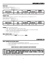
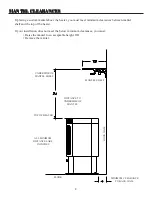
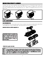
Minimum clearances to combustibles:

Top of heater....................................36"
Sides of heater....................................8"
Front of heater..................................42"
Rear of heater.....................................4"

FIGURE 3. Minimum Clearances

FIGURE 3. Minimum Clearances

FIGURE 3. Minimum Clearances

FIGURE 3. Minimum Clearances

FIGURE 3. Minimum Clearances

36"

8"

8"

4"

42"

Ensur

Ensur

Ensur

Ensur

Ensure the minim

e the minim

e the minim

e the minim

e the minimum c

um c

um c

um c

um clear

lear

lear

lear

learances sho

ances sho

ances sho

ances sho

ances shown in FIGURE 3 ar

wn in FIGURE 3 ar

wn in FIGURE 3 ar

wn in FIGURE 3 ar

wn in FIGURE 3 are maintained f

e maintained f

e maintained f

e maintained f

e maintained for

or

or

or

or

accessibility f

accessibility f

accessibility f

accessibility f

accessibility for pur

or pur

or pur

or pur

or purposes of ser

poses of ser

poses of ser

poses of ser

poses of servicing and pr

vicing and pr

vicing and pr

vicing and pr

vicing and proper oper

oper oper

oper oper

oper oper

oper opera

a

a

a

ation. Left and r

tion. Left and r

tion. Left and r

tion. Left and r

tion. Left and right

ight

ight

ight

ight

c

cc

cclear

lear

lear

lear

learances ar

ances ar

ances ar

ances ar

ances are deter

e deter

e deter

e deter

e determined w

mined w

mined w

mined w

mined when f

hen f

hen f

hen f

hen facing the fr

acing the fr

acing the fr

acing the fr

acing the front of the hea

ont of the hea

ont of the hea

ont of the hea

ont of the heater

ter

ter

ter

ter.....

WARNINGWARNINGWARNINGWARNINGWARNING

WARNINGWARNINGWARNINGWARNINGWARNING

Maintain these clearances to

Maintain these clearances to

Maintain these clearances to

Maintain these clearances to

Maintain these clearances to
ensure adequate space

ensure adequate space

ensure adequate space

ensure adequate space

ensure adequate space
around air opening for

around air opening for

around air opening for

around air opening for

around air opening for
proper operation.

proper operation.

proper operation.

proper operation.

proper operation.

Summary of Contents for Ambiance B9945N

Page 1: ...cannot reac ou cannot reac ou cannot reac ou cannot reach y h y h y h y h your gas supplier our gas supplier our gas supplier our gas supplier our gas supplier call call call call call the fire depart...

Page 2: ...erative that control compartments burners and circulating air passageways of the appliance be kept clean IMPORTANT SAFETY INFORMATION 3 4 PRODUCT FEATURES 4 SPECIFICATIONS 5 CONTENTS 5 ITEMS REQUIRED...

Page 3: ...ghsurfacetemperatureandshouldstayawaytoavoidburns orclothingignition Youngchildrenshouldbecarefullysupervisedwhentheyareinthesameroomwiththeappliance IMPOR IMPOR IMPOR IMPOR IMPORT T T T TANT SAFETY I...

Page 4: ...ials gasolineandotherflammablevaporsandliquids Anysafetyscreenorguardremovedforservicingmustbereplacedpriortooperatingtheheater Thisvent freegasheaterisintendedtobesmokeless Iflogsappeartosmoke turnof...

Page 5: ...VENT SKIN IRRIT O PREVENT SKIN IRRIT O PREVENT SKIN IRRIT O PREVENT SKIN IRRITA A A A ATION FR TION FR TION FR TION FR TION FROM LOOSE FIBERS OM LOOSE FIBERS OM LOOSE FIBERS OM LOOSE FIBERS OM LOOSE F...

Page 6: ...which complies with local codes Sediment trap Pipe sealant approved for use with Pipe wrench propane LPG resistant to sulfur compounds CODES CODES CODES CODES CODES Adheretoalllocalcodesorintheirabse...

Page 7: ...n uction uction pr pr pr pr pro o o o ovide vide vide vide vide adequate combustion and ventilation air by one of the methods described in the adequate combustion and ventilation air by one of the met...

Page 8: ...learances between mantel shelf and the top of the heater If your installation does not meet the below minimum clearances you must Raise the mantel to an acceptable height OR Remove the mantel ALL MINI...

Page 9: ...o allow full gas when permitted by local codes Only use pipe of 1 2 or greater diameter to allow full gas when permitted by local codes Only use pipe of 1 2 or greater diameter to allow full gas when...

Page 10: ...r for leaks using soap and water solution after completing connection DO NOT USE AN OPEN FLAME The heater regulator controls the burner pressure which should be checked at the pressure test point loca...

Page 11: ...s pine cones pine cones pine cones pine cones pine cones v v v v ver er er er ermiculite or r miculite or r miculite or r miculite or r miculite or roc oc oc oc ock w k w k w k w k wool to the hea ool...

Page 12: ...ights the pilot If Piezo fails thenlightthepilotusingmatches Refertomatchlightinginstructions page14 Whenlightingthepilot follow theseinstructionsexactly BEFORE LIGHTING smell all around the appliance...

Page 13: ...knob clockwise to ON 10 Wait about one minute then turn burner switch D to ON It will take a few minutes for the thermopile located on top of the pilot to heat up NOTE If unit is equipped with remote...

Page 14: ...terisinoperationandshouldjusttouchthetopofthe thermocouple tip FIGURE 9 Ifthepilotflamedoesnottouchthethermocouple then the main burner is unlikely to function reliably FIGURE 10 WARNING WARNING WARNI...

Page 15: ...ction Annual Cleaning Inspection Inspect and clean burner air intake holes Inspect and clean all burner ports Inspect ODS pilot for operation and accumulation of lint at air intake holes Verify flame...

Page 16: ...ASSEMBLY REPLACEMENT PARTS HEATER ASSEMBLY REPLACEMENT PARTS HEATER ASSEMBLY REPLACEMENT PARTS HEATER ASSEMBLY REPLACEMENT PARTS HEATER ASSEMBLY REPLACEMENT PARTS 5 3 9 7 6 18 10 4 17 15 16 8 12 11 1...

Page 17: ...774 LOUVER FRAME 1 11 B24457 CONTROL DOOR 1 12 89899 BRASS KNOB 1 13 83323 8 32 x 3 8 MACHINE SCREW 1 14 24800 WINDOW FRAME BRACKET BOTTOM 2 15 24799 WINDOW FRAME BRACKET TOP 2 16 69236 WINDOW FRAME A...

Page 18: ...18 BURNER LOG ASSEMBLY BURNER LOG ASSEMBLY BURNER LOG ASSEMBLY BURNER LOG ASSEMBLY BURNER LOG ASSEMBLY 11 1 17 15 16 14 3 2 8 7 9 10 6 4 5 12 13...

Page 19: ...198 CONTROL VALVE NATURAL 1 81202 CONTROL VALVE LIQUID PROPANE 1 4 83464 10 32 x 3 8 PH HD MACHINE SCREW 4 5 89937 BURNER GAS LINE 31 ORIFICE NAT 1 89938 BURNER GAS LINE 49 ORIFICE L P 1 N S 83172 10A...

Page 20: ...gnitor Ventilateroom Stopusingodor causing products while heater is running Locate and correct all leaks Appliance burning vapors from paint hair spray glues etc Gas leak Appliance produces unwanted o...

Page 21: ...roblem will stop after a few hours of operation Run the heater with the damper open if you have one or open a window for the first few hours Log heater is intended to be smokeless Turn OFF heater and...

Page 22: ...9945 THIS OPTIONAL F40 BLOWER KIT IS AVAILABLE WHERE YOU PURCHASED THIS HEATER OR YOU CAN ORDER DIRECT FROM THE FACTORY BY CONTACTING THE PARTS DEPARTMENT AT THE NUMBER AND ADDRESS ON THE BACK PAGE OF...

Page 23: ...ING DIAGRAM FOR GENERATOR ASSEMBLY WIRING DIAGRAM FOR GENERATOR ASSEMBLY 50 60 70 80 90 21 10 32 c 50 60 70 80 90 21 10 32 c MODEL WSK60 WALL SWITCH KIT OPTIONAL KITS FOR THE 9945 OPTIONAL KITS FOR TH...

Page 24: ...F STANDARD WIRING FROM FACTORY STANDARD WIRING FROM FACTORY STANDARD WIRING FROM FACTORY STANDARD WIRING FROM FACTORY STANDARD WIRING FROM FACTORY WIRING OF THE RCK60 REMOTE CONTROL KIT WIRING OF THE...

Page 25: ...IT THE RCK60 REMOTE CONTROL KIT THE RCK60 REMOTE CONTROL KIT Remember the Rocker Switch must be turned to OFF while using the Wall Switch PILOT O F F PILOT O N Sit E A TP TH TP TH ROCKER SWITCH CONTRO...

Page 26: ...26 NOTES NOTES NOTES NOTES NOTES...

Page 27: ...R WAR THIS WARRANTY IS EXPRESSLY IN LIEU OF OTHER WAR THIS WARRANTY IS EXPRESSLY IN LIEU OF OTHER WAR THIS WARRANTY IS EXPRESSLY IN LIEU OF OTHER WAR THIS WARRANTY IS EXPRESSLY IN LIEU OF OTHER WAR RA...

Page 28: ...EP IN A SAFE PLACE FOR FUTURE REFERENCE WHEN WRITING ALWAYS GIVE THE FULL MODEL NUMBER WHICH IS ON THE NAMEPLATE ATTACHED INSIDE THE FRONT OF THE HEATER WHEN ORDERING REPAIR PARTS OR OPTIONS ALWAYS GI...

Reviews: