24
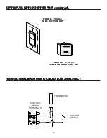
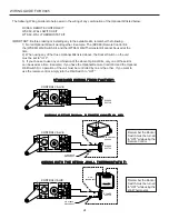
The following Wiring Guide is to help assist in the wiring of any combination of the Optional Kit listed below:
RCK60 - REMOTE CONTROL KIT
WSK60 - WALL SWITCH KIT
WTK60 - WALL THERMOSTAT KIT
IMPORTANT: Before ordering or installing any to the available kits, remember the following...
1) Not all Optional Kits will work together. Example: The (RCK60) Remote Control Kit,
the (WSK60) Wall Switch Kit, and the (WTK60) Wall Thermostat Kit cannot be used at the
time.
2) When using any of the three Optional Kits listed above, the Rocker Switch on the unit
must be set to "OFF".
3) If you choose to use any combination of the above Optional Kits, only one of those kits
can be used at a time. Example: If you have the Optional Remote Control Kit and the Optional
Wall Switch Kit, operation of the unit must be controlled by one or the other. If you want to
use the remote control, simply turn the Wall Switch to "OFF".
STANDARD WIRING FROM FACTORY:
STANDARD WIRING FROM FACTORY:
STANDARD WIRING FROM FACTORY:
STANDARD WIRING FROM FACTORY:
STANDARD WIRING FROM FACTORY:
WIRING OF THE RCK60 - REMOTE CONTROL KIT:
WIRING OF THE RCK60 - REMOTE CONTROL KIT:
WIRING OF THE RCK60 - REMOTE CONTROL KIT:
WIRING OF THE RCK60 - REMOTE CONTROL KIT:
WIRING OF THE RCK60 - REMOTE CONTROL KIT:
WIRING WITH THE WTK60 - WALL THERMOSTAT KIT:
WIRING WITH THE WTK60 - WALL THERMOSTAT KIT:
WIRING WITH THE WTK60 - WALL THERMOSTAT KIT:
WIRING WITH THE WTK60 - WALL THERMOSTAT KIT:
WIRING WITH THE WTK60 - WALL THERMOSTAT KIT:
PILOT
O
F
F
PILOT
O
N
S
it
E
A
TP TH
TP
TH
ROCKER
SWITCH
CONTROL VALVE
PILOT
O
F
F
PILOT
O
N
S
it
E
A
TP TH
TP
TH
ROCKER
SWITCH
CONTROL VALVE
REMOTE CONTROL
SENSOR
PIGGYBACK
DISCONNECT
PILOT
O
F
F
PILOT
O
N
S
it
E
A
TP TH
TP
TH
ROCKER
SWITCH
CONTROL VALVE
WALL
THERMOSTAT
PIGGYBACK
DISCONNECT
50 60 70 80 90
21
10
32
c
50 60 70 80 90
21
10
32
c
Remember the Rocker
Switch must be turned
to "OFF" while using the
Remote Control.
Remember the Rocker
Switch must be turned
to "OFF" while using the
Wall Thermostat.
WIRING GUIDE FOR 9945

