


170761-UIM-B-0406
Unitary Products Group
9
SECTION VIII: SYSTEM OPERATION
REQUIRED CONTROL SETUP
IMPORTANT: The following steps must be taken at the time of
installation to insure proper system operation.
1.
Consult system wiring diagram to determine proper wiring for
proper system configuration.
2.
If hot heat pump configuration is desired, change HOT HEAT
PUMP jumper to ON position.
3.
If installation includes a fossil fuel furnace, change FFUEL jumper
to ON position.
4.
Set low temperature cutout (LTCO) and balance point (BP) jump-
ers as desired.
5.
Verify proper system functionality. Confirm room thermostat opera-
tion including fault code display capability.
6.
Upon completion of installation, verify that no fault codes are
stored in memory. Clear the fault code memory if necessary.
ANTI-SHORT CYCLE DELAY
The control includes a five-minute anti-short cycle delay (ASCD) timer
to prevent the compressor from short cycling after a power or thermo-
stat signal interruption. The ASCD timer is applied when the control is
first powered from the indoor unit thermostat and immediately following
the completion of a compressor run cycle. The compressor and the out-
door fan will not operate during the five minutes that the timer is active.
The ASCD timer can be bypassed by connecting the TEST terminals
for three seconds while the thermostat is calling for compressor opera-
tion (Y1 input signal energized).
LOW VOLTAGE DETECTION
The control monitors the transformer secondary (24 VAC) voltage and
provides low voltage protection for the heat pump and its components.
In particular, the control prevents contactor chatter during low voltage
conditions. If the voltage drops below approximately 19 VAC, the con-
trol will continue to energize any relays that are already energized but
will not energize any additional relays until the voltage level increases.
If the voltage drops below approximately 16 VAC, the control will imme-
diately de-energize the relay outputs and will not energize any relays
until the voltage level increases. The control will store and display the
appropriate fault codes when low voltage conditions occur.
CRANKCASE HEATER
The control energizes the crankcase heater terminal (CCH) whenever
line voltage is applied to the control and the outdoor fan is not on. If the
compressor is equipped with a crankcase heater, it will be energized
from the CCH terminal of the control.
TEST INPUT
The control includes a TEST input connector that can be used for vari-
ous testing functions during installation and service. The TEST input
connector is shown in Figures 10 and 13. The following table summa-
rizes the behavior of the control when the two TEST pins are con-
nected. More detailed descriptions of the various functions are included
in other sections of this document.
LED DIAGNOSTIC INDICATORS
The control includes two LED’s that display various types of diagnostic
information. LED1 is red and LED2 is green. The location of the LED’s
is shown in Figures 10 and 13. These LED’s are used to display opera-
tional mode, status, and fault information.
OPERATIONAL MODE DETECTION
The control can be used in a variety of applications including heat
pumps and air conditioners with modulating compressors. The control
uses various inputs to determine the proper mode of operation.
It looks for the presence of a reversing valve connected to the RV and
RVG terminals to determine if it should operate as a heat pump or an air
conditioner. If the reversing valve is not connected, the control will not
operate in the heat pump mode. The control senses the reversing valve
loads and determines the operational mode each time power to the
control is cycled.
The control also senses the connections that are made to the M, M1,
and M2 terminals and determines the correct operational mode for the
control. This is done each time power to the control is cycled. There-
fore, it is important that no loads be attached to the M1 or M2 terminals
of the control. Incorrect system behavior could result.
IMPORTANT: Do not connect any loads to the M1 or M2 terminals of
the control. Incorrect system behavior could result.
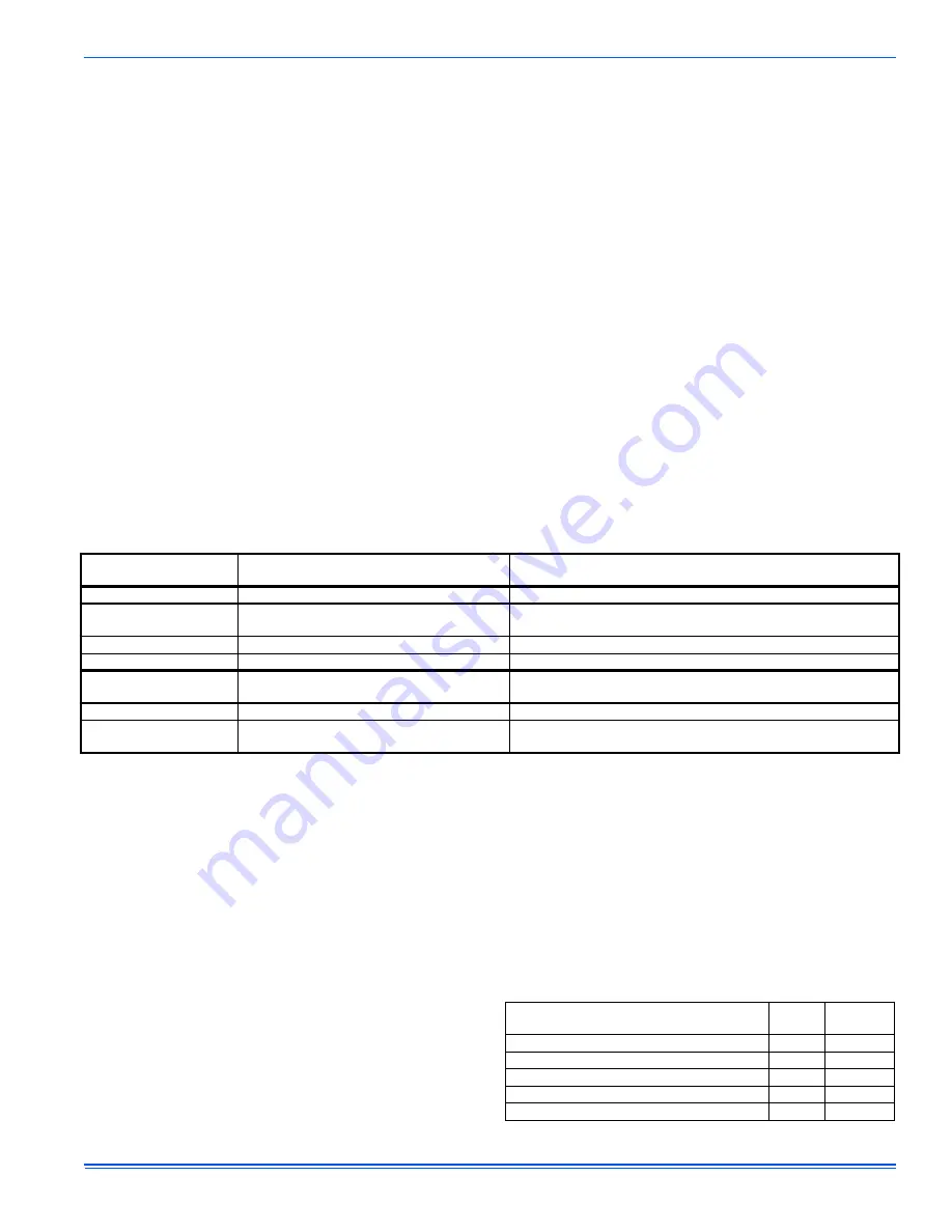
OPERATIONAL MODE DISPLAY
The control will display its active operational mode using the onboard
LED’s when the TEST pins are connected while no thermostat signals
are energized. See Table 3. The control will display the operational
mode as long as the TEST pins are shorted and no thermostat signals
are energized. When the TEST pin short is removed, the control will
return to normal LED displays. The X/L output will be energized (with
the number of flashes corresponding to the active defrost curve) while
the operational mode is displayed. For example, if defrost curve 2 is
active, the X/L output will be energized with two flashes while the oper-
ational mode is being displayed on the LED’s.
TABLE 2: TEST Input Functionality
Duration of
connection (seconds)
Control behavior with no
thermostat signals present
Control behavior with thermostat signals present
Less than 2
No response
No response
2-6
Display operational mode
Bypass ASCD. If Y1 is present and high-pressure switch is
closed, contactors will be energized.
Clear soft lockout
Clear soft lockout
Clear hard lockout
Clear hard lockout
More than 6
Display operational mode
Energize X/L with active defrost curve flash code
Initiate defrost cycle ignoring the liquid line and outdoor ambient temp.
Energize X/L with active defrost curve flash code
Connection removed
Resume normal LED display
Terminate defrost as normal or until O signal is energized.
Connection not removed
Display operational mode
Energize X/L with active defrost curve flash code
Continue defrost cycle and X/L flash code until
TEST connection removed.
TABLE 3: Operational Mode Display
Operational Mode
LED1
(Red)
LED2
(Green)
Heat Pump
ON
Air Conditioner
OFF
Single-Stage Compressor
1
Reciprocating Two-Stage Compressor
2
Scroll Two-Stage Compressor
3
---


