
15
Unitary Products Group
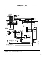
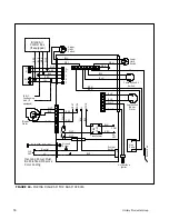
WIRING DIAGRAMS
FIGURE 17
-- WIRING DIAGRAM FOR DGAT SERIES
W
G
RH
Y
Wall
Thermostat
Upper
Limit Switch
Lower
Limit
Switch
Combustion Air
Switch
Combustion
Blower
Motor
Hot Surface
Ignitor
Gas
Valve
Blower
Motor
System
Switch
To Earth Ground
Neutral
L1
115
VAC
To A/C
Condensing
Unit (If equipped)
Incoming Power Must
Be Polarized. Observe
Color Coding
NE
UT
RA
LS
Ground
Screw
HE
A
T
COOL
L1
XFM
R
COM
24
VAC
RED
BLK
BRN
WHT
WHT
BLK
BLU
RED
LO
A
D
LI
N
E
WHT
WHT
BLK
S
ens
or
R
od
BLK
BRN
BRN
BLK
BLU
BLU
GRN
ORG
BLU
GRY
W
G
R
Y
C
BL
K
BL
K
BL
K
GRN
WH
T
RE
D
YEL
BLK
GRN
WHT
Transformer
YEL
RED
WH
T
Blend Air
Control Box
(If equipped)
1
3 4 5 6 7 8 9
2
1
2
3
4
5
6
7
8
9
1
2
3
4
5
6
1
2
Summary of Contents for DLAS
Page 23: ...23 Unitary Products Group...













![Roberts Gorden Combat UHD[S] 150-400 Specifications preview](http://thumbs.mh-extra.com/thumbs/roberts-gorden/combat-uhd-s-150-400/combat-uhd-s-150-400_specifications_1469644-1.webp)


