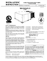
General ................................................................................ 1
Inspection............................................................................. 1
Reference ............................................................................ 1
Approvals ............................................................................. 1
Nomenclature....................................................................... 2
INSTALLATION
Limitations ............................................................................ 3
Location ............................................................................... 3
Condensate Drainage Precaution ....................................... 3
Rigging and Handling .......................................................... 3
Clearances........................................................................... 3
Ductwork .............................................................................. 4
Filters ................................................................................... 4
Condensate Drain ................................................................ 4
Service Access..................................................................... 4
Thermostat........................................................................... 4
Power and Control Wiring.................................................... 4
Electric Heaters.................................................................... 4
Compressors........................................................................ 4
OPERATION
Cooling System.................................................................. 10
Preliminary Operation Cooling........................................... 10
Cooling Sequence of Operation ........................................ 10
Heating Sequence of Operation ........................................ 10
Heat Anticipator Setpoints ..................................................11
Checking Supply Air CFM...................................................11
Defrost Sequence of Operation ......................................... 12
Secure Owner’s Approval .................................................. 13
MAINTENANCE
Normal Maintenance.......................................................... 13
TABLES
No. Description Page
1
Unit Application Data ..................................
3
2
Electrical Data.............................................
5
3
Physical Data ..............................................
6
4
Point Loads .................................................
8
5
Supply Air Br Performance .........................
9
6
Accessory Static Resistances ....................
9
7
Blower Motor and Drive Data .....................
10
8
Heat Anticipator Setting ..............................
11
9
Blower Motor Pulley Adjustment.................
11
FIGURES
No. Description Page
1
Center of Gravity.........................................
3
2
Recommended Drain Piping.......................
4
3
Typical Field Wiring.....................................
5
4
Dimensions and Clearances.......................
7
5
Point Loads .................................................
8
6
Pressure Drop versus Supply Air CFM.......
11
7
Defrost Initiation Times ...............................
12
8
Ambient Modified Time/Temp. Control........
13
TABLE OF CONTENTS
B
C
C
B
A
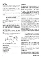
PRODUCT NOMENCLATURE
PRODUCT GENERATION
C = 3rd Generation
D = 4th Generation
E = 5th Generation
PRODUCT CATEGORY
B = Single Package Heat Pump
(Air Cooled)
PRODUCT IDENTIFIER
CB = Heat Pump
VOLTAGE CODE
-T = 208/230-3-60
-W = 460-3-60
-X = 575-3-60
090 = 7-1/2 Ton
120 = 10 Ton
9
0
0
-
T
FACTORY INSTALLED
HEAT
A = No Heat Installed
NOMINAL COOLING CAPACITY
511.06-N2W
2
Unitary Products Group


