272312-UIM-A-0407
Unitary Products Group
25
ADJUSTMENT OF TEMPERATURE RISE
The temperature rise, or temperature difference between the return air
and the heated supply air from the furnace, must be within the range
shown on the furnace rating plate and within the application limitations
as shown in Table 8.
DIRECT DRIVE MOTORS
Adjustment of Fan Control Settings
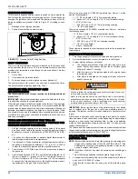
This furnace is equipped with a time-on/time-off heating fan control. The
fan on delay is fixed at 30 seconds. The fan off delay has 4 settings (60,
90, 120 and 180 seconds). The fan off delay is factory set to 120 sec-
onds. The fan-off setting must be long enough to adequately cool the
furnace, but not so long that cold air is blown into the heated space. The
fan-off timing may be adjusted by positioning the jumper on two of the
four pins as shown in Figure 30.
Continuous Blower Operation
The blower will run continuously whenever the wall thermostat fan
switch is in the "ON" position. The furnace blower will run at the speed
selected on the "FAN SPEED" jumpers on the main control board (HI
COOL, LO COOL, HI HEAT or LO HEAT).
Intermittent Blower Cooling
On cooling/ heating thermostats with a fan switch, when the fan switch
is set in the auto position and the thermostat calls for cooling, a circuit is
completed between the R, Y and G terminals. The motor is energized
through the Y cool terminal and runs on the “HI COOL” or “LO COOL”
speed selected on the board. The fan off setting is fixed at 60 seconds
for maximum cooling efficiency furnace control.
Intermittent Blower Heating
On cooling/ heating thermostats with a fan switch, when the fan switch
is set in the auto position and the thermostat calls for heating, a circuit is
completed between the R and W terminals. The indoor fan motor is
energized through the W1or W2 heat terminal and runs on the “HIGH
HEAT or LOW HEAT” speed selected on the furnace control board.
TROUBLESHOOTING
The following visual checks should be made before troubleshooting:
1.
Check to see that the power to the furnace and the ignition control
module is ON.
2.
The manual shut-off valves in the gas line to the furnace must be
open.
3.
Make sure all wiring connections are secure.
4.
Review the sequence of operation. Start the system by setting the
thermostat above the room temperature. Observe the system’s
response. Then use the troubleshooting section in this manual to
check the system’s operation.
FURNACE CONTROL DIAGNOSTICS
The furnace has built-in, self-diagnostic capability. If a system problem
occurs, a blinking LED shows a fault code. The LED can flash red,
green or amber to indicate various conditions. It is located behind a
clear view port in the blower compartment door.
The control continuously monitors its own operation and the operation
of the system. If a failure occurs, the LED will indicate the failure code. If
the failure is internal to the control, the light will stay on continuously. In
this case, the entire control should be replaced, as the control is not
field repairable.
Flash sequence codes 1 through 10 are as follows: LED will turn “on”
for 1/4 second and “off” for 1/4 second. This pattern will be repeated the
number of times equal to the code. For example, six “on” flashes equals
a number 6 fault code. All flash code sequences are broken by a 2 sec-
ond “off” period.
SLOW GREEN FLASH:
Normal operation.
SLOW AMBER FLASH:
Normal operation with call for heat.
RAPID RED FLASH:
Twinning error, incorrect 24V phasing. Check
twinning wiring.
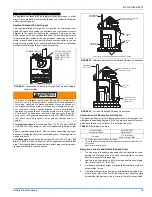
The temperature rise, or temperature difference between the return
air and the supply (heated) air from the furnace, must be within the
range shown on the furnace rating plate and within the application
limitations shown in Table 8 “RATINGS AND PHYSICAL/ELECTRI-
CAL DATA”.
The supply air temperature cannot exceed the “Maximum Supply
Air Temperature” specified in these instructions and on the fur-
nace rating plate. Under NO circumstances can the furnace be
allowed to operate above the Maximum Supply Air Temperature.
Operating the furnace above the Maximum Supply Air Temperature
will cause premature heat exchanger failure, high levels of Carbon
Monoxide, a fire hazard, personal injury, property damage, and/or
death.
Do not energize more than one motor speed at a time or damage to
the motor will result.
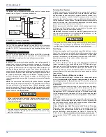
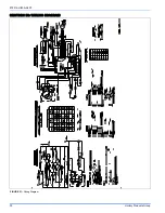
FIGURE 30:
Furnace Control Board
HI COOL
LO HEAT
EAC-H
L1
XFMR
NEUTRALS
HUM
60
90
120
180
BLOWER DELAY
Y/Y2
W2
R
G
C
Y1
LO COOL
REMOTE
SWITCH
FA
N
SPEED
LO
COOL
LO
HEA
T
HI
COOL
W/W1
HI
HEA
T
W2
DELA
Y
OFF
10
MIN
15
MIN
20
MIN
HI HEAT
YELLOW - MED LOW
BLACK - HI
RED - LOW
BLUE - MED HI
CONTINUOUS
FAN SPEED
JUMPER
W1 - W2
DELAY
JUMPER
FAN OFF
ADJUSTMENT
JUMPER


