background image

272312-UIM-A-0407

22

Unitary Products Group

PRESSURE SWITCHES

This furnace is supplied with two pressure switches, which monitor the
flow through the combustion air/vent piping system. This switches de-
energize the ignition control module and the gas valve if any of the fol-
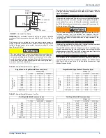
lowing conditions are present. Refer to Figure 27 for tubing connec-
tions.

1.

Blockage of vent piping or terminal.

2.

Failure of combustion air blower motor.

LIMIT CONTROLS

There is a high temperature limit control located on the furnace vesti-
bule panel near the gas valve. This is an automatic reset control that
provides over temperature protection due to reduced airflow. This may
be caused by:

1.

A dirty filter.

2.

If the indoor fan motor should fail.

3.

Too many supply or retrn registers closed or blocked off.

The control module will lockout if the limit trips 5 consecutive times.
Control will reset & try ignition again after 1 hour. 

SECTION VIII: START-UP AND 

ADJUSTMENTS

The initial start-up of the furnace requires the following additional
procedures:

IMPORTANT: 

All electrical connections made in the field and in the fac-

tory should be checked for proper tightness.

When the gas supply is initially connected to the furnace, the gas piping
may be full of air. In order to purge this air, it is recommended that the
ground union be loosened until the odor of gas is detected. When gas is
detected, immediately retighten the union and check for leaks. Allow
five minutes for any gas to dissipate before continuing with the start-up
procedure. Be sure proper ventilation is available to dilute and carry
away any vented gas.

TOOLS AND INFORMATION THAT WILL BE 

REQUIRED IN ORDER TO PROPERLY PERFORM THE 

FURNACE STARTUP PROCEDURE.

1.

Call the local gas supplier to obtain heating value of the natural
gas. If you cannot obtain the heating valve of the gas from the gas
supplier, you may use a default value of 1030 BTU/SCF (38.8 MJ /
m³). 

2.

You will need a thermometer or portable digital thermometer to
read the supply and return air temperatures. 

3.

You will need a U-tube manometer or digital equipment that has
the ability to read pressures between 0 – 15” in.w.c (0 - 3.73 kPa)
in order to measure the gas line and the manifold pressures. 

4.

You will need a 3/32” Allen wrench for the pressure port plugs in
the gas valve. 

5.

You will need 2 pieces of 1/8” (0.3 cm) ID flexible tubing that is 12”
(30 cm) in length, 2 – pieces of 1/8” (0.3 cm) tubing that are 4”
(10.0 cm) in length, a 1/8” (0.3 cm) tee and a 1/8” (0.3 cm) adapter
to connect the U-tube manometer or the digital pressure measur-
ing equipment to the gas valve pressure ports.

There is an accessory kit (1PK0601) available from Source 1, which
has the following items:

1 - 12” (30 cm) length x 1/8” (0.3 cm) diameter tubing

2 – pieces of 4” (10 cm) length x 1/8” (0.3 cm) diameter tubing

1 - 5/16” (0.8 cm) tee

1 – 5/16” (0.8 cm) x 1/8” (3.175 mm) reducing coupling

1 – 1/8” (0.3 cm) adapter

There is a accessory kit (1PK0602) available from Source 1, which has
the following items:

12” (30 cm) length x 1/8” (0.3 cm) diameter tubing

2 – pieces of 4” (10 cm) length x 1/8” (0.3 cm) diameter tubing

1 - 5/16” (0.8 cm) tee

1 – 5/16” (0.8 cm) x 1/8” (0.3 cm) reducing coupling

1 – 1/8” (0.3 cm) adapter

1 - Dwyer – Manometer

These items are required in order to properly perform the required star-
tup procedure.

IGNITION SYSTEM SEQUENCE

1.

Turn the gas supply ON at external valve and main gas valve.

2.

Set the thermostat above room temperature to call for heat.

3.

System start-up will occur as follows:

a.

The induced draft blower motor will start and come up to
speed. Shortly after inducer start-up, the hot surface igniter
will glow for about 17 seconds.

b.

After this warm up, the ignition module will energize (open)
the main gas valve.

c.

After flame is established, the supply air blower will start in
about 30 seconds.

IMPORTANT: 

Burner ignition may not be satisfactory on first startup

due to residual air in the gas line or until gas manifold pressure is
adjusted. The ignition control will make 3 attempts to light before lock-
ing out.

With furnace in operation, check all of the pipe joints, gas valve connec-
tions and manual valve connections for leakage using an approved gas
detector, a non-corrosive leak detection fluid, or other leak detection
methods. Take appropriate steps to stop any leak. If a leak persists,
replace the component.
The furnace and its equipment shutoff valve must be disconnected from
the gas supply piping system during any pressure testing of that system
at test pressures in excess of 1/2 PSI (3.45 kPa).

CALCULATING THE FURNACE INPUT 

(NATURAL GAS)

NOTE: 

Burner orifices are sized to provide proper input rate using natu-

ral gas with a heating value of 1030 BTU/Ft

3

 (38.8 MJ/m

3

). If the

heating value of your gas is significantly different, it may be nec-
essary to replace the orifices.

NOTE: 

Front door of burner box must be secured when checking gas

input. 

1.

Turn off all other gas appliances connected to the gas meter.

2.

At the gas meter, measure the time (with a stop watch) it takes to

use 2 cubic ft. (0.0566 m

3

.) of gas.

3.

Calculate the furnace input by using one of the following equa-
tions.

 FIGURE 27:  

Pressure Switch Tubing Routing

FIRE OR EXPLOSION HAZARD

Failure to follow the safety warnings exactly could result in serious
injury, death or property damage.

Never test for gas leaks with an open flame. Use a commercially
available soap solution made specifically for the detection of leaks
to check all connections. A fire or explosion may result causing
property damage, personal injury or loss of life.

Summary of Contents for AHT8-UH

Page 1: ...RING DIAGRAM 30 LIST OF FIGURES Dimensions 6 Typical Attic Installation 7 Typical Suspended Furnace Crawl Space Installation 7 Side Return Cutout Markings 8 Gas Valve 8 Upflow Gas Piping 8 Horizontal...

Page 2: ...s from combustible materials as listed under Clearances to Combustibles in Table 1 Provide clearances for servicing ensuring that service access is allowed for both the burners and blower These models...

Page 3: ...d Never store items such as the following on near or in contact with the fur nace 1 Spray or aerosol cans rags brooms dust mops vacuum cleaners or other cleaning tools 2 Soap powders bleaches waxes or...

Page 4: ...t the specified external static pressure and within the air temperature rise specified on the nameplate Table 2 is a guide for determining whether the rectangular duct system that the furnace is being...

Page 5: ...plenum On all installations without a coil a removable access panel is recommended in the outlet duct such that smoke or reflected light would be observable inside the casing to indi cate the presenc...

Page 6: ...essibility IMPORTANT If an external mounted filter rack is being used see the instructions provided with that accessory for proper hole cut size HORIZONTAL MODELS IMPORTANT This furnace may be install...

Page 7: ...removed and a new plenum installed that is the proper size for the new furnace Attach the return plenum to the furnace inlet duct flanges This is typi cally through the use of S cleat material when a...

Page 8: ...fer to Table 15 SECTION IV GAS PIPING GAS SAFETY IMPORTANT Plan your gas supply before determining the correct gas pipe entry Use 90 degree service elbow s or short nipples and con ventional 90 degree...

Page 9: ...e gas valve body is a very thin casting that cannot take any external pressure Never apply a pipe wrench to the body of the gas valve when installing piping A wrench must be placed on the octag onal h...

Page 10: ...o the proper gas orifice size when the furnace is installed Do not attempt to drill out any orifices to obtain the proper orifice size Drilling out a gas orifice will cause misalignment of the burner...

Page 11: ...ty is corrected Refer to FURNACE DIAGNOSTICS section of the User s Information Maintenance Service Manual provided with this furnace for symptoms of reversed power supply polarity LOW VOLTAGE CONTROL...

Page 12: ...lt Common is optional when used with batteries Thermostat Installer Setup Number 1 System Type must be set to 6 2 Heat 2 Cool Conventional R 24 Volt Hot Heat XFMR W2 Second Stage Heat RC 24 Volt Hot C...

Page 13: ...BSG Bonnet Sensor Bonnet Sensor Optional BS Bonnet Sensor W2 Second Stage Auxiliary Heat W2 Second Stage Auxiliary Heat AUX Auxiliary Heat E W1 First Stage Auxiliary Heat E W1 First Stage Auxiliary H...

Page 14: ...gas supplies must be provided as specified with these instruc tions Since the furnaces are side by side with no space between gas supplies must enter on the right and left respectively All gas piping...

Page 15: ...wers will come on in the selected continuous fan speed and will stay on until the G signal is removed SECTION VI VENT SYSTEM VENT SAFETY This Category I furnace is designed for residential application...

Page 16: ...ese instructions Approved Modular Homes must be vented with an approved roof jack and may not be common vented with other appliances VENTING Category I venting consists of vertically venting one or mo...

Page 17: ...se masonry chimney kits 3 The chimney must extend at least three 3 ft 0 91 cm above the highest point where it passes through a roof of a building and at least two 2 feet higher than any portion of th...

Page 18: ...tion should be located where it will not be affected by wind gusts light snow airborne leaves or allow recirculation of flue gases 4 Termination should be located where it will not be damaged or expos...

Page 19: ...anufacturer s instructions Dampers Louvers and Grilles Canada Only 1 The free area of a supply air opening shall be calculated by sub tracting the blockage area of all fixed louvers grilles or screens...

Page 20: ...horizontally from the burner level of the appliance Refer to COMBUSTION AIR SOURCE FROM OUTDOORS and VENT AND SUPPLY AIR SAFETY CHECK in these instructions for additional information and safety check...

Page 21: ...mounted on the burner assembly If the temperature around the burner exceeds the set point the ignition control and the gas valve are de energized The operation of this control indicates a malfunction...

Page 22: ...m Source 1 which has the following items 1 12 30 cm length x 1 8 0 3 cm diameter tubing 2 pieces of 4 10 cm length x 1 8 0 3 cm diameter tubing 1 5 16 0 8 cm tee 1 5 16 0 8 cm x 1 8 3 175 mm reducing...

Page 23: ...at the gas meter times a barometric pressure and temperature correction factor of 0 960 times 3600 then divided by the time it took to measure 0 10 m3 of gas from the gas meter For Propane LP Gas mul...

Page 24: ...h low and high have been calibrated at the factory Additional pressure adjustment should not be necessary If adjustment is necessary set to the following specifications After adjustment check for gas...

Page 25: ...eration Start the system by setting the thermostat above the room temperature Observe the system s response Then use the troubleshooting section in this manual to check the system s operation FURNACE...

Page 26: ...mit switch has opened its normally closed contacts and has remained open for more than five minutes This condition is usually caused by a failed blower motor or blower wheel 12 RED FLASHES This code i...

Page 27: ...the difference in ESP values in the table 0 60 w c 150 Pa 0 50 w c 125 Pa to obtain a percentage 0 58 0 50 0 60 0 50 0 8 Multiply percentage by airflow difference to obtain airflow reduction 0 8 X 70...

Page 28: ...50 1440 1430 1390 1360 1310 1270 1220 1150 41 6 41 1 40 8 40 5 39 4 38 5 37 1 36 0 34 5 32 6 Low 1260 1260 1260 1260 1250 1200 1150 1110 1070 1010 35 7 35 7 35 7 35 7 35 4 34 0 32 6 31 4 30 3 28 6 80...

Page 29: ...640 1550 1460 56 6 55 5 54 7 53 8 51 0 49 8 48 4 46 4 43 9 41 3 Medium 1440 1440 1430 1420 1400 1380 1340 1300 1220 1150 40 8 40 8 40 5 40 2 39 6 39 1 37 9 36 8 34 5 32 6 Low 1220 1230 1230 1230 1200...

Page 30: ...272312 UIM A 0407 30 Unitary Products Group SECTION IX WIRING DIAGRAM FIGURE 31 Wiring Diagram...

Page 31: ...272312 UIM A 0407 Unitary Products Group 31 NOTES...

Page 32: ...t to change without notice Printed in U S A 272312 UIM A 0407 Copyright by York International Corp 2007 All rights reserved Supersedes 167185 UIM C 0806 Unitary 5005 Norman Product York OK Group Drive...

Reviews: