background image

29

PARTS DIAGRAM & LIST (continued)

UGP-E20H08-030903

Oven Rheostat Connectin Wire for UGP-24V; 20V  EC

UGP-E20H08-030904

Oven Option Switch Connecting Wire for UGP-24V; 20V  EC

UGP-E20H08-030905

PCB Power In Harness for UGP-24V; 20V  EC

UGP-E20H08-030906

Oven Control Wire for UGP-24V; 20V  EC

UGP-E20H08-030907

Broiler Control Wire for UGP-24V; 20V  EC

UGP-E20H08-030908

High Temperature Limit Connecting Wire for UGP-24V; 20V  EC

38

UGP-E24F01-031600

Top Heating Element Rheostat for UGP-24V; 20V  EC

39

UGP-E24H08-120900

Top Heating Element Rheostat mount bracket for UGP-24V; 20V  EC

40

UGP-E20F08-214500

Control Panel Deflector forUGP-20V  EC

41

UGP-E24F08-026100

Top Heating Element Support Spring for UGP-20V; 24V EC  

42

UGP-E24F08-025100

Top Heating Element Support Bolt for UGP-20V; 24V EC  

43

UGP-E20H08-030200

Microcrystalline Glass for UGP-20V  EC

44

UGP-G20A01-091501

120 V Temperature Fan for UGP-20V PC1; EC S/S;W;B

45

UGP-E20F08-020100

Microcrystalline Glass Edging for UGP-20V  EC

46

UGP-G20H08-011500-Z Backsplash ASSY for UGP-20V  EC

47

UGP-G20C01-022000

Cooktop Back Connection Plate for UGP-24V; 20V PC1; EC S/S;W;B

48

UGP-G20C01-070604

Cavity- Top Plate for UGP-20V EC S/S;W;B

49

UGP-C20A01-091201

Oven/Broiler Heating Element Support for UGP-20V; 24VEC S/S;W;B

50

UGP-E24F01-091001

Broiler Heating Element 240V 2100W for UGP-20V; 24V EC S/S;W;B

UGP-E24F01-074200

Chimney Outside Plate for UGP-20V; 24V EC S/S;W;B

UGP-E24F01-075000

Chimney Inside Plate for UGP-20V; 24V EC S/S;W;B

52

UGP-E24F08-200900

Cooling Fan Motor for UGP-20V; 24V EC S/S;W;B

53

UGP-G20C01-180100

Oven Interior Light for UGP-20V EC S/S;W;B

54

UGP-E20F01-070302

Cavity- Back Panel for UGP-20V EC S/S;W;B

55

UGP-G20A01-070800

Oven Insulation for UGP-20V EC S/S;W;B

56

UGP-E20F08-072000

Back Panel for UGP-20V EC S/S;W;B

57

UGP-E24F08-072000

Service Door for UGP-20V; 24V EC S/S;W;B

58

UGP-E20F08-072900

Oven Insulation (back) for UGP-20V EC S/S;W;B

61

UGP-G20C01-215100

Broil Grill for UGP-24V; 20V PC1; EC S/S;W;B

62

UGP-G20C01-215000

Broil Tray for UGP-24V; 20V PC1; EC S/S;W;B

63

UGP-G20H08-071900

Roasted Net (Oven Rack) for UGP-20V PC1; EC S/S;W;B

64

UGP-E20F01-091201

Oven Heating Element 240V 2100W for UGP-20V; 24V EC S/S;W;B

65

UGP-E20F01-034500

Wiring Block Bracket for UGP-20V EC S/S;W;B

66

UGP-E20F01-070700

Cavity- Bottom Panel (Oven Floor) for UGP-20V EC S/S;W;B

67

UGP-G20C01-111100

Door Hinge Plate for UGP-24V; 20V PC1; EC S/S;W;B

68

UGP-E20H08-180300

Harness for UGP-20V EC S/S;W;B

UGP-E24F01-076200

240C Temperature Limit Switch for UGP-24V; 20V EC S/S;W;B

UGP-C36R05-076200

50C Temperature Limit Switch for UGP-24V; 20V EC S/S;W;B

70

UGP-E20F01-106400

Oven Junction Box for UGP-24V; 20V EC S/S;W;B

71

UGP-G20A14-160100

Power Cord  for UGP-24V; 20V EC S/S;W;B

72

UGP-E20H08-022100

Microcrystalline Glass Support (front) for UGP-20V  EC

73

UGP-E20F08-024100

Top Heating Element Support Left for UGP-20V  EC

73

UGP-E20F08-024200

Top Heating Element Support Right for UGP-20V  EC

74

UGP-E20F08-022000

Microcrystalline Glass Support (rear) for UGP-20V  EC

75

UGP-E24F08-022400

Top Heating Element 1800W for UGP-20V; 24V  EC

76

UGP-E24F08-022300

Top Heating Element 1200W for UGP-20V; 24V  EC

UGP-G20H08-100400S/S Oven door ASSY for UGP-20V PC1; EC S/S

UGP-G20H08-100400B

Oven door ASSY for UGP-20V PC1; EC B

51

69

no

t s

ho

w

on 

dr

aw

ing

UGP-G20H08-100400W Oven door ASSY for UGP-20V PC1; EC W

ITEM # PART #

DESCRIPTION

UGP-G20C01-071002

Side Panel S/S (Left & Right) T=0.5 for UGP-24V; 20V PC1; EC S/S

UGP-G20C01-071002-01 Side Panel White (Left & Right) T=0.5 for UGP-24V; 20V PC1; EC W

UGP-G20C01-071002-02 Side Panel Black (Left & Right) T=0.5 for UGP-24V; 20V PC1; EC B

2

UGP-G20A01-070500

Cavity- Right Plate for UGP-24V; 20V PC1; EC S/S;W;B

3

UGP-G20A01-212500

Anti-tip Bracket for UGP-24V; 20V PC1; EC S/S;W;B

4

UGP-G20A01-210200

Weight Block (2.5 kg) for UGP-24V; 20V PC1; EC S/S;W;B

5

UGP-G20C01-071500

Oven Feet for UGP-24V; 20V PC1; EC S/S;W;B

6

UGP-G20A01-071100

Oven Feet Mounting Plate for UGP-24V; 20VPC1; EC S/S;W;B

7

UGP-G24A01-070200

Front Plate- Beam for UGP-24V PC1; EC S/S;W;B

8

UGP-G24C01-072101

Burner Mounting Plate for UGP-24V PC1; EC S/S;W;B

9

UGP-G20A01-070400

Cavity- Left Plate for UGP-24V; 20V PC1; EC S/S;W;B

10

UGP-G24C01-070102

Front Plate for UGP-24V PC1; EC S/S;W;B

11

UGP-G20A01-120700

Sliding Rail Component (set of 2) for UGP-24V; 20V PC1; EC S/S;W;B

12

UGP-G24C03-120500-02 Drawer Body for UGP-24V PC1; EC S/S;W;B

13

UGP-G24C02-120200-04 Drawer- S/S Inside Plate for UGP-24V PC1; EC S/S

UGP-G24H08-120100

Drawer- S/S Outside Plate for UGP-24V PC1; EC S/S

UGP-G24H08-120100-02 Drawer- Black Outside Plate for UGP-24V PC1; EC B

UGP-G24H08-120100-01 Drawer- White Outside Plate for UGP-24V PC1; EC W

15

UGP-G24B11-101900

Oven/Broiler Door Handle S/S for UGP-24V PC1; EC S/S;W;B

16

UGP-G24C01-071200

Cavity Sealing Strip-2 (long) for UGP-24V PC1; EC S/S;W;B

17

UGP-G24H08-100500

LOWE Inner Glass Door for UGP-24V PC1; EC S/S;W;B

18

UGP-G24B01-101401

Door Top Cover for UGP-24V PC1; EC S/S;W;B

19

UGP-E24H08-031000

Temperature indicator light for UGP-24V; 20V EC

20

N/A

21

N/A

22

N/A

23

UGP-G24B11-101900

Oven/Broiler Door Handle S/S for UGP-24V PC1; EC S/S;W;B

24

N/A

25

UGP-G20B01-100800

Door- Inside Glass Support (Left) for UGP-24V; 20V PC1: EC S/S;W;B

25

UGP-G20B01-100900

Door- Inside Glass Support (Right) for UGP-24V; 20VPC1; EC S/S;W;B

26

UPG-G20B01-101200

Hinge Support (Left) for UGP-24V; 20V PC1; EC S/S;W;B

26

UGP-G20B01-101300

Hinge Support (Right) for UGP-24V; 20V PC1; EC S/S;W;B

27

UGP-G20B01-110003

Door Hinge for UGP-24V PC1; EC S/S;W;B

28

UGP-G24H08-101100

LOWE Door Inside Window for UGP-24V PC1; EC S/S;W;B

29

UGP-G20A20-030100-09 Knob #20 short stem for UGP-24V; 20V EC S/S

30

UGP-G20A06-030200-10 Knob Ring #6 (Bezel) for UGP-24V; 20V PC1; EC S/S;W;B (set of 5)

31

UGP-E24H08-030300

Control Panel for UGP-24V PC1; EC S/S

32

UGP-E24F08-031002

Oven indicator light (blue) for UGP-24V; 20V  EC S/S

33

UGP-E24H08-170200

Oven Option Switch for UGP-24V; 20V EC

34

UGP-G20H08-091700

Temperature Fan Cover for UGP-20V; 24V PC1; EC S/S;W;B

35

UGP-E24F08-190501

Rheostat mount bracket for UGP-24V; 20V  EC

36

UGP-G24H08-170200

Fan Switch ASM for UGP-24V; 20V PC1; EC S/S;W;B

37

UGP-E24H08-030900

Oven Rheostat for UGP-24V; 20V  EC

UGP-E20H08-030901

Main PCB for UGP-24V; 20V  EC

UGP-E20H08-030902

Temperature Probe for UGP-24V; 20V  EC

UGP-E20H08-030903

Oven Rheostat Connectin Wire for UGP-24V; 20V  EC

UGP-E20H08-030904

Oven Option Switch Connecting Wire for UGP-24V; 20V  EC

1

14

no

t s

ho

w

on 

dr

aw

ing

Summary of Contents for UGP-20V EC S/S

Page 1: ...OCT21V1 OWNER S GUIDE serial number PRESTIGE 20 ELECTRIC CONVECTION RANGE 20 50 8 cm MODEL NUMBER UGP 20V EC S S 4009900 ...

Page 2: ...al features Determine from a study of your range which of the instructions given in this booklet pertain to your range This booklet gives valuable instructions covering the installation adjustment and use of your range How to Obtain Service and or Parts When your range does not operate in accordance with the instructions in the manual you should contact the dealer in your immediate vicinity for se...

Page 3: ...cked with the appliance To check if the device is installed and engaged properly Carefully tip the range forward The Anti Tip device should engage and prevent the range from tipping over If this range is removed for any reason service or cleaning etc it must be replaced as outlined in the installation instructions before placing the range back in operation Making sure the anti tip bracket is insta...

Page 4: ...ANTI TIP LOCATION 13 PARTS AND FEATURES 15 OPERATION OF RANGE 16 OPERATION OF OVEN 17 CARE AND MAINTENANCE 20 CLEANING THE RANGE 23 TROUBLESHOOTING GUIDE 25 WIRING DIAGRAM 26 PARTS DIAGRAM AND LIST 27 WARRANTY 30 APPLIANCE INFORMATION 31 NOTES 31 PRODUCT REGISTRATION 31 CONTACT US 31 TABLE OF CONTENTS ...

Page 5: ...hese instructions are not meant to cover every possible condition and situation that may occur Common sense and caution must be practiced when installing operating and maintaining the appliance Record in the space provided below the Model No and Serial No of this appliance These numbers are found on the serial plate located at the bottom drawer Model No ______________________ Serial No ___________...

Page 6: ...se this appliance as a space heater to heat or warm the room Wear proper apparel Loose fitting or hanging garments should never be worn while using the appliance Do not let clothing or other flammable materials contact surface burners or interior surfaces of the oven until they have had sufficient time to cool Never modify or alter the construction of the range Do not remove leveling legs panels w...

Page 7: ... bodily harm death or property damage TO REDUCE THE RISK OF TIPPING OF THE RANGE THE RANGE MUST BE SECURED BY A PROPERLY INSTALLED ANTI TIP BRACKET PROVIDED WITH THE RANGE TO CHECK IF THE DEVICE IS INSTALLED AND ENGAGED PROPERLY CAREFULLY TIP THE RANGE FORWARD THE ANTI TIP DEVICE SHOULD ENGAGE AND PREVENT THE RANGE FROM TIPPING OVER REFER TO THE INSTALLATION INSTRUCTIONS PACKAGED WITH THE ANTI TIP...

Page 8: ...ue to unintentional contact with the cookware the handle of a cookware should be positioned so that it is turned inward and does not extend over adjacent surface burners Never leave the surface burners unattended Boilovers may cause smoking greasy spill overs may catch fire or a pan which has boiled dry may melt Do not place hands between the spring tension hinge and the oven door frame when you a...

Page 9: ... push against any of the edges of the range in an attempt to slide it into or out of the installation Pushing or pulling a range rather than using a lift jack also increases the possibility of bending the leg spindles or the internal coupling connectors NOTE The instructions appearing in this owner s guide are not meant to cover every possible condition and situation that may occur Common sense an...

Page 10: ...ave all of the parts listed below 1 backsplash 2 anti tip brackets 2 oven racks 1 broiler griddle 1 broiler tray 2 screws for backsplash 1 instruction installation manual Clean the interior surface with lukewarm water using a soft cloth Have your range installed and properly grounded by a qualifies installer in accordance with the installation instructions Do not attempt to repair or replace any p...

Page 11: ... backsplash to the rear part of the cooktop as shown in the diagram 2 Secure the backsplash to the cooktop from the back using the 2 Phillips head screws provided as shown in the diagram HOW TO INSTALL THE BACKSPLASH ...

Page 12: ...e range Verify the anti tip device has been properly installed and engaged Engage the range to the anti tip device by ensuring the anti tip device is re engaged when the range is moved Re engage the anti tip device if the range is moved Do not operate the range without the anti tip device in place and engaged See installation instructions for details Failure to do so can result in death or serious...

Page 13: ...ed at the back of the range ANY OPENINGS IN THE WALL BEHIND THE UNIT AND IN THE FLOOR UNDER THE UNIT MUST BE SEALED Note Due to potential hazards it is recommended that storage cabinets NOT be installed above the cooking surface IN THE EVENT OVERHEAD CABINETS ARE INSTALLED THE MAXIMUM DEPTH OF CABINETS INSTALLED ABOVE COOKING TOPS SHOULD BE 13 20 WALL CLEARANCES ANTI TIP LOCATION ...

Page 14: ...14 Anti Tip Bracket Location WALL CLEARANCES ANTI TIP LOCATION continued ...

Page 15: ...15 1 Backsplash with integrated oven vents 2 Cooktop 3 Control panel 4 Oven Handle 5 Oven Door 6 Storage Drawer Handle 7 Storage Drawer 8 Leveling Legs 4 1 2 3 4 5 6 7 8 PARTS FEATURES ...

Page 16: ...y using items similar to knives sharp object rings jewelry Avoid storing items that can melt or possibly catch fire on the glass cooktop even if not in use In the even the cooktop is accidentally turned on and or heat from the oven vent may cause items to melt or ignite Never cook directly on the glass always use appropriate cookware BURNER CONTROL KNOB The range comes with four burners To operate...

Page 17: ...mance of any cooking systems Therefore emphasis must be placed on the importance of using proper cookware Use cooking vessels with flat bottoms and tight fitting lids to conserve energy and shorten cooking times Only certain types of glass glass ceramic ceramic earthenware or other glazed cookware are suitable for use on glass cooktops Manufacturers suggest using low to medium heat selections when...

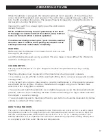
Page 18: ...o the Off position and switch the broil oven rocker switch to O or standby position mode Note Broil has no modulation just Max temp In order to broil use the following steps 1 Place the meat on the broil grid in broiler pan Always use the grid so that the fat drips into the broiler pan otherwise the juices may catch on fire Do not broil without using the broiler pan 2 Position the broiler pan on t...

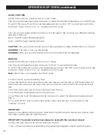
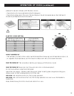
Page 19: ...emperature valve F To regulate the temperature set the chosen number onto the control knob indicator VERY IMPORTANT The oven broil shall be used always with the door closed VERY IMPORTANT Never obstruct the oven vent slots on the backsplash Do not broil without using the broiling pan Important Use always suitable protective gloves when inserting removing the broiling pan shelves pans on the cookin...

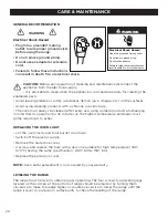
Page 20: ... highest temperature eliminates most grime reducing it to ashes REPLACING THE OVEN LIGHT Let the oven cavity and broil burner cool down Switch off the electric supply Remove the protective cover Unscrew and replace the bulb with a new one suitable for high temperature 300 570 F having the same specifications 240V 60Hz 15W E14 Replace the protective cover NOTE Oven bulb replacement is not covered b...

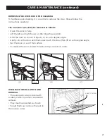
Page 21: ... door as shown in figure C on a 45 degree angle Gently close the door until the hooks touch the door then lift at a 45 degree angle Set the door on a soft flat surface To replace the door repeat the above steps in reverse order OVEN RACK INSTALLATION AND REMOVAL The oven racks are provided with a safety catch to prevent accidental removal They must be inserted as shown To pull them out remove the ...

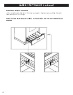
Page 22: ... DRAWER Lift the small hook to the left of the drawer upwards simultaneously pushing the right hook downwards see image DO NOT STORE FLAMMABLE MATERIAL IN THE OVEN OR IN THE BOTTOM STORAGE DRAWER CARE MAINTENANCE continued ...

Page 23: ...n abrasive cleaner or any abrasive action Abrasive action will scratch the knobs If the knobs become loose on the valve stem spread the valve stem slightly with a small screwdriver Using Commercial Oven Cleaners Commercial oven cleaners may be used on porcelain lined ovens however many cleaners are very strong and it s essential to follow instructions carefully Be sure to wear rubber gloves to pro...

Page 24: ... guards aluminum control panels and painted surfaces Never use harsh abrasives or cleaning powders that may scratch or mar the surface Make sure the cleaners and cleaning materials are suitable for use on the area to be cleaned Always keep cleaning materials in a safe place Never use a sharp metal scraper to clean glass porcelain or painted surfaces Repair Parts When repair parts are needed contac...

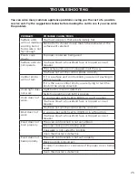
Page 25: ...tive Switch operating oven light is broken Oven does not work Is your rocker switch set to BROIL or in off position You have blown a household fuse or tripped a circuit breaker You have not set the control knobs correctly Broil does not work Is your rocker switch set to OVEN or in off position You have blown a household fuse or tripped a circuit breaker Food does not broil properly The oven contro...

Page 26: ...26 WIRING DIAGRAM ...

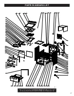
Page 27: ...27 Please visit our website www uniqueappliances com to view a PDF version of the schematics which will allow you to zoom in out PARTS DIAGRAM LIST ...

Page 28: ... G20B11 101900 Oven Broiler Door HandleS S for UGP 20V PC1 EC S S W B 16 UGP G20C01 071200 Cavity Sealing Strip 2 long for UGP 20V PC1 EC S S W B 17 UGP G20H08 100500 LOWEInner Glass Door for UGP 20V PC1 EC S S W B 18 UGP G20B01 101401 Door Top Cover for UGP 20V PC1 EC S S W B 19 UGP E24H08 031000 Temperatureindicator light for UGP 24V 20V EC 20 N A 21 N A 22 N A 23 G20B11 101900 Oven Broiler Door...

Page 29: ...022300 Top Heating Element 1200W for UGP 20V 24V EC UGP G20H08 100400S S Oven door ASSYfor UGP 20V PC1 EC S S UGP G20H08 100400B Oven door ASSYfor UGP 20V PC1 EC B 51 69 not shown on drawing UGP G20H08 100400W Oven door ASSYfor UGP 20V PC1 EC W ITEM PART DESCRIPTION UGP G20C01 071002 SidePanel S S Left Right T 0 5 for UGP 24V 20V PC1 EC S S UGP G20C01 071002 01 SidePanel White Left Right T 0 5 for...

Page 30: ...nd all other warranties conditions representations or guarantees including any warranties conditions representations or guarantees under any Sale of Goods Act or like legislation or statute is hereby expressly excluded Save as herein provided Unique shall not be responsible for any damages to persons or property including the unit itself howsoever caused or any consequential damages arising from t...

Page 31: ...icing of your fridge easy and efficient please record the following informa tion for future reference Model Serial Number Purchased From Date Purchased APPLIANCE INFORMATION CONTACT US Toll free 1 877 427 2266 or 1 905 827 6154 available during regular business hours 8 30 am to 4 30 pm EST Website www uniqueappliances com Email info UniqueAppliances com Please visit our website at https uniqueappl...

Page 32: ... 2021 Unique Appliances Ltd 2245 Wyecroft Road 5 Oakville Ontario Canada L6L 5L7 www UniqueAppliances com ...

Reviews: