background image

43

7


OPTION

43

OP

TION

Chapter

7

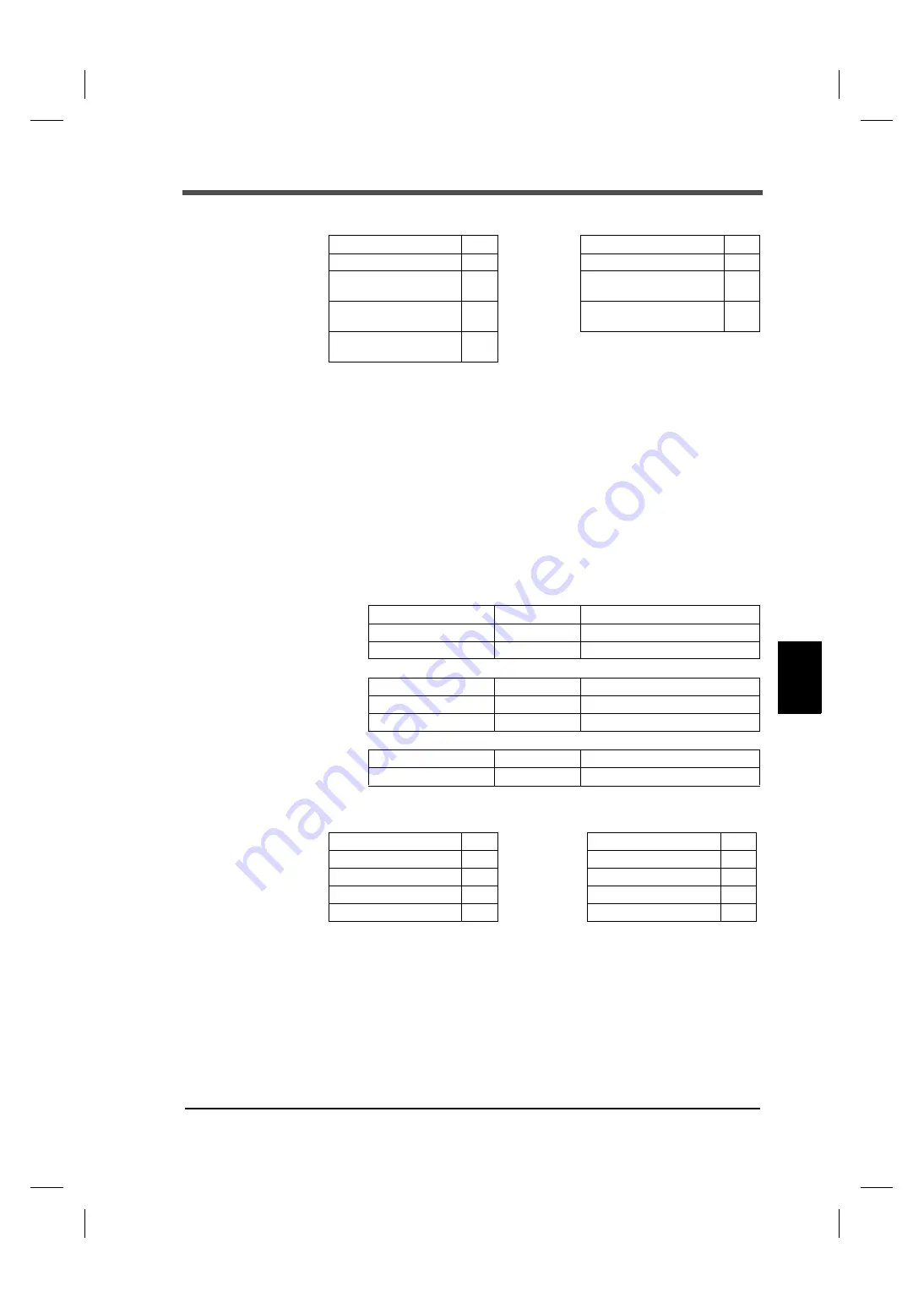
Example) Read the contents of linked with indicated value (address 30004).

Keep in mind that the relative address for reading the linked with indicated value is 0x03.
The example shows the case where the indicated value of the F331 is as follows:

 05 (0x05) Write single coil

A slave coil is changed to ON or OFF.
If broadcast (0) is specified, all slave coils of the same address are rewritten. 
To request, specify the coil address and output value.
0xFF and 0x00 correspond to ON, and 0x00 and 0x00 correspond to OFF.
No change is made with other data, which are considered as improper data.

Example) Turn on the hold/judge ON (address 00001).

Keep in mind that the relative address for writing in the hold/judge ON is 0x00.
In the case of normal writing, the response becomes identical to the request.

* To confirm coil execution, judge as complete with a normal response.

[Request]

Function

04

[Response]

Function

04

Start address; higher

00

Number of data bytes

02

Start address; lower

03

Linked with indicated value
(higher)

03

Number of registers; 
higher

00

Linked with indicated value
(lower)

E8

Number of registers; 
lower

01

Linked with indicated value: 1000 (0x03E8)

[Request]

Function

1

 byte

0x05

Start address

2

 byte

s

0x0000 - 0xFFFF

Output data

2

 byte

s

0x0000 or 0xFF00

[Response]

Function

1

 byte

0x05

Start address

2

 bytes

0x0000 - 0xFFFF

Output data

2

 byte

s

0x0000 or 0xFF00

[Error response]

Error code

1

 byte

0x85 (fu 0x80)

Exception code

1

 byte

01 or 02 or 03

[Request]

Function

05

[Response]

Function

05

Start address; higher

00

Start address; higher

00

Start address; lower

00

Start address; lower

00

Hold/judge ON; higher

FF

Hold/judge ON; higher

FF

Hold/judge ON; lower

00

Hold/judge ON; lower

00

Summary of Contents for F331

Page 1: ...OPERATION MANUAL 26MAY2014REV 1 02 DIGITAL INDICATOR F331 ...

Page 2: ...ocedures Also carefully store this instruction manual so that it can be referred to at any time Safety Precautions Installation maintenance and inspection of the F331 should be performed by personnel having technical knowledge of electricity In order to have an F331 Weighing Indicator used safely notes I would like you to surely follow divide into and and are indicated by the following documents N...

Page 3: ...of cables to the signal input output terminals Connection to the ground terminal For connection to the signal input output terminals check the signal names and pin assignment numbers and then carry out wiring properly To take measures against lightning surge install a lightning surge protector optionally available Before applying power carefully check the wiring etc Use a power supply voltage and ...

Page 4: ...ue 0 2 to 0 6 N m For sensors external inputs outputs and options use shielded cables For turning on off the power be sure to keep intervals of 5 seconds or more After power on make sure to warm up the F331 for at least 30 minutes or more before use If the F331 is not used by the specified method its protective performance may be impaired Maintenance When performing maintenance disconnect the powe...

Page 5: ...61000 4 5 Lightning Surge Immunity is met by the F331 body in combination with a lightning surge protector For conformity with EMC Directives attach a lightning surge protector to the power supply line Shape Connection of a USB connector For conformity with EMC Directives attachment of a cap for USB connector EN55011 EN61000 4 2 EN61000 4 3 EN61000 4 4 EN61000 4 5 EN61000 4 6 EN61000 4 8 EMC Direc...

Page 6: ...nt handled within EU borders The six substances are lead mercury cadmium hexavalent chromium PBB polybrominated biphenyls and PBDE polybrominated diphenyl ethers 6 4 2 5 3 1 L N IN OUT L N PT 2 PE S 24AC ST PT BE FM Lightning surge protector F331 DC IN 11 12 To 24V DC power supply Be sure to ground of the lightning surge protector Without grounding it will not function as a lightning surge protect...

Page 7: ...k type 9 2 6 Connection of the external input 9 3 SETTING METHOD 10 3 1 Preparation of PC 10 PC hardware requirement 10 Installation of a USB driver 10 Connection of USB 10 The check of a virtual COM port 10 3 2 Starting of the F331 PC application software 10 Installation of the F331 PC application software 10 The injection of a power supply 11 Starting of the F331 PC application software 11 Speci...

Page 8: ...fference of the maximum point and the minimum point is held 20 5 9 Digital zero function 21 Digital zero by key operation 21 Digital zero by external signal input 21 5 10 ZERO key valid invalid 21 5 11 Display frequency 21 6 EXTERNAL INPUT OUTPUT SIGNALS 22 6 1 Connector pin assignments 22 6 2 External input signals 22 Hold Judge edge input 22 Digital zero edge input 22 6 3 External output signals...

Page 9: ...etting value LOCK Calibration value LOCK 65 8 SPECIFICATIONS 66 8 1 Specifications 66 Analog section 66 Display section 66 Setting section 66 External signals 67 Interface 67 Option 67 General specifications 69 Accessories 69 8 2 Dimensions 70 When the BCD output option is equipped 71 When the D A converter option is equipped 72 When the RS 485 option is equipped 73 When the RS 232C option is equi...

Page 10: ...kage The packaging box contains the following Make sure to check them before use 1 2 About connectable devices 1 OUTLINE F331 body 1 F331 quick manual 1 Short bar 1 When RS 485 option is selected BCD output connector 1set When BCD output option is selected ...

Page 11: ...ks during hold detection OK Lights when OK is ON Numerical display The two types of display are provided 1 Indicated value 2 Error Message display See 9 1 Error Message display on page 77 Setting key Forcibly zeros the indicated value by the digital zero function USB connector with a cap This is an interface for connection with a personal computer PC Status display Numerical Setting key display US...

Page 12: ...body M4 8 binding head machine screw with a toothed washer Signal input output terminal block This terminal block is used for input output of control signals and input of strain gauge sensor signals Terminal block assignment 1 to 5 Terminal for connecting a strain gauge sensor 1 SHIELD 2 EXC 3 SIG 4 EXC 5 SIG 6 7 Terminals for inputting Hold Judge signals 6 COM 7 IN1 Hold Judge input 6 8 Terminals...

Page 13: ... LO LL 6 COM 9 OUT1 Initial value HI 10 OUT2 Initial value LO 11 to 13 Terminals for inputting power The input voltage is DC24V 15 11 12 13 FG Options slot One option board can in stall in the option slot BCD parallel data output BCO D A converter current output DAI RS 485 interface 485 RS 232C interface 232 ...

Page 14: ... connection to the signal input output terminals check the signal names and pin assignment numbers and then carry out wiring properly After wiring be sure to mount the attached terminal block cover Otherwise it may cause an electric shock Before applying power carefully check the wiring etc Do not touch any signal input output terminal while applying power Doing so may cause electric shocks or mal...

Page 15: ...on screwdriver etc 4 Insert the wire into the hole so as not to loosen the end 5 Tighten the screw with the screwdriver 6 Lightly pull the wire to check that it is clamped securely Connectable wires are 0 21 3 31mm2 AWG12 24 Recommendable tightening torque is 0 2 to0 6 Nm 7 Insert the wire connected plug into the F331 body and tighten the screws two The number of pins is 13 Turn counterclockwise H...

Page 16: ...in gauge sensor 6 wire strain gauge sensor For connecting a 6 wire strain gauge sensor short circuit EXC and S and EXC and S Signal input output 1 2 3 4 5 EXC SIG EXC SIG 2 3 4 5 Strain gauge sensor SHIELD 1 terminal block With mark The excitation voltage is 5V With no mark The excitation voltage is 2 5V BV5 Point EXC EXC SIG SIG SHIELD IN OUT IN OUT 2 5 F331 1 3 4 EXC EXC SIG SIG SHIELD IN OUT IN...

Page 17: ...applied because it may cause an electric shock Be aware that the voltage drops depending on the wire thickness and length Also never input AC power source Doing so will cause a failure Since the F331 has no power switch install a breaker Be sure to ground the protective ground terminal to prevent electric shocks and failures by static electricity The frame and protective ground terminal are conduc...

Page 18: ... applying external voltages to the signal input circuit Use external elements which withstands Ic 10mA or above Leakage current from external element must be 30μA or below COM Spark killer Load F331 Inside Spark killer DC Varistor Load Relay Vext Supply an external power source for a relay drive Output data Tr OFF OFF ON ON Output transistor status 9 10 6 Power supply AC Power supply power source ...

Page 19: ...ichip com Drivers VCP htm Connection of USB Please the cap of the USB connector and connects a USB cable The USB connector of the F331 is mini B TYPE The check of a virtual COM port Please check the virtual COM port number which the F331 is connected from the device manager of PC 3 2 Starting of the F331 PC application software Installation of the F331 PC application software Setting up the F331 b...

Page 20: ...tware will start by executing an EXE file If there is no shortcut on the desktop please run the EXE file from the destination folder Specification of a COM port Please specify virtual COM port that is confirmed on COM port in the window menu The check of a indicating value Check if indicating value on the F331 is displayed It is a Logging screen at the first time starting EXE file The indicating v...

Page 21: ...Digital low pass filter 2 12 0 3 1 6 2 12 Hz P 18 Hold mode 0 OFF 0 OFF 1 Sample 2 Peak 3 Valley 4 P P P 19 ZERO key valid invalid 0 Valid 0 Valid 1 Invalid P 21 Display frequency 2 20 0 5 1 10 2 20 times sec P 21 External output selection Output selection 1 3 HI 0 OK 1 NG 2 HH 3 HI 4 LO 5 LL P 23 Output selection 2 4 LO 0 OK 1 NG 2 HH 3 HI 4 LO 5 LL Item Initial value Setting range Page Zero cali...

Page 22: ... zero scale 0000 9999 to 9999 P 30 D A full scale 1000 9999 to 9999 P 30 RS 485 communication mode 0 Command 0 Command 1 Continuous1 2 Continuous2 3 Modbus RTU P 33 RS 485 I F setting Baud rate 4 19200 0 1200 1 2400 2 4800 3 9600 4 19200 5 38400 bps P 33 Length of character 1 8bit 0 7bit 1 8bit Parity bit 2 even 0 None 1 odd 2 even Stop bit 0 1bit 0 1bit 1 2bit Delimiter 0 CR 0 CR 1 CR LF RS 485 I...

Page 23: ...ual loads cannot be applied For example Gain will be automatically decided by registering the values indicated as follows For load 2 001mV V 100 0kgf For pressure 2 002mV V 10 00kgf cm2 and For torque 2 502mV V 15 00kgf m Actual load calibration This approach provides calibration by applying an actual load to the strain gauge sensor and setting the actual load value This calibration is without lit...

Page 24: ...The actual load calibration uses the following procedure Set the decimal place Omissible if no desired value is present Set the zero point of the strain gauge sensor Set the span gain point of the strain gage sensor 4 3 Decimal place This function sets the Position of decimal point 4 4 Equipment ID F331 can be set Equipment ID for identification Equipment ID has Indicator ID and Loadcell ID Settin...

Page 25: ...yed alternately OFF condition Indicated value LO limit value LL ON condition Indicated value LL limit value Indicated value displayed alternately OFF condition Indicated value LL limit value OK ON condition HH HI LO and LL are OFF OK lights up OFF condition When either of HH HI LO or LL is ON NG ON condition When OK is OFF OK lights turned off OFF condition When OK is ON The example of HI LO limit...

Page 26: ...n conditions HH ON condition Indicated value HH limit value OFF condition Indicated value HH limit value hysteresis value HI ON condition Indicated value HI limit value OFF condition Indicated value HI limit value hysteresis value LO ON condition Indicated value LO limit value OFF condition Indicated value LO limit value hysteresis value LL ON condition Indicated value LL limit value OFF condition...

Page 27: ...enient when you cannot obtain zero by unloading the equipment for some reason or when you want to give offset Indicated value to be displayed Actual indicated value Digital offset setting value 5 6 Moving average filter This function restrains the indicated value from fluctuating by moving averaging the A Dconverted data The moving average times can be selected in the range of OFF 1 time 512 times...

Page 28: ...m when the hold signal is inputted to when the indicated value is held t2 Time from when the hold signal is cancelled to when the indicated value returns to tracking t3 Minimum reset signal width required for canceling the hold t4 Time after updating a hold value until it holds HOLD LED is blinked after HOLD start for the 1st time Time Indicated value Sensor input value HOLD input OFF ON t1 to t3 ...

Page 29: ...g chart t1 Time from when the hold signal is inputted to when the indicated value is held t2 Time from when the hold signal is cancelled to when the indicated value returns to tracking t3 Minimum reset signal width required for canceling the hold t4 Time after updating a hold value until it holds HOLD LED is blinked after HOLD start for the 1st time Time Indicated value Sensor input value HOLD t2 ...

Page 30: ...ey valid invalid This function validates invalidates the operation of the ZERO key 5 11 Display frequency The Display frequency function is used to select the times the indicated values are displayed per second A D conversion count is fixed to 300 per second Display Message description Invalid ZERO key operations ZERO Digital zero OFF ON Turn ON for 50 msec or more The digital zero function is res...

Page 31: ... the hold mode is OFF it operates as a judgment signal of comparison timing However it is unrelated when comparison timing condition is ALWAYS or NZ Digital zero edge input The digital zero works to zero the indicated value 6 EXTERNAL INPUT OUTPUT SIGNALS Signal input output 6 7 8 9 10 IN1 IN2 OUT1 OUT2 7 8 9 10 COM 6 terminal block OFF Hold ON ON OFF Hold OFF ON OFF Judge ON ON OFF Judge OFF ON O...

Page 32: ...utputs is selectable by setting OUT1 Output selection 1 OUT2 Output selection 2 Select from OK NG HH HI LO and LL OK NG HH HI LO LL Each signal turns ON when the comparison condition is met See 5 1 HI LO limit comparison on page 16 to 5 4 Comparison timing on page 18 External output selection Output selection 1 Output selection 2 0 OK 1 NG 2 HH 3 HI 4 LO 5 LL ...

Page 33: ...ng and recording Assembling connector 1 Align the connector and each screw two in the groove in one case 2 Put the other case on it and fit the cases together 3 Tighten each M2 8 pan head machine screw two Tighten each M2 10 pan head machine screw two Be aware that the M2 10 pan head machine screw should be combined with a washer 7 OPTION A16 B16 A1 B1 Case two Screw two Connector M2 10 pan head m...

Page 34: ...element must be 30μA or below Internal transistor status Output data Negative Positive 0 OFF ON 1 ON OFF Output pin level Output data Negative Positive 0 H L 1 L H Through logic switching pin B14 Output COM 24VRTN COM Input 24V F331 Sink type PLC input unit etc Plus common type A2 to A13 B2 to B13 A1 B1 12V Vceo 30V max Ic 50mA max F331 PLC output unit etc Sink type Output COM Ic Input COM A1 B1 A...

Page 35: ...d OVER It is outputted at the time of over scale LOAD LOAD OFL1 or OFL2 STROBE Strobe pulses are outputted in synchronization with BCD data Read data using the rising edges 1 0 of the pulses The setting of BCD data update rate can be changed No Signal No Signal A1 COM B1 COM A2 Out 1 B2 Out 1000 A3 Out 2 B3 Out 2000 A4 Out 4 B4 Out 4000 A5 Out 8 B5 Out 8000 A6 Out 10 B6 Out A7 Out 20 B7 Out Output...

Page 36: ...made according to the changes in sensor input signal BCD data update rate selection Normaly BCD data update synchronous the A D conversion 300 times sec When the BCD input equipment is low ability and can not read out the high rate of 300 times sec set the BCD data update rate is low BCD external output selection Output signal can be assigned Select from OK NG HH HI LO and LL When level input is O...

Page 37: ...d 300times sec Resolution 1 10000 Over range 2 4 to 21 6mA Zero drift Within 0 5μA Gain drift Within 50ppm Non linearity Within 0 05 FS Not including the drift of the analog input section Connector M3 screw type terminal block two pole Compatible solderless terminal within 5 9mm Tightening torque 0 6N m Current output terminals Terminals for obtaining current signal 4 to 20mA can be obtained Gain ...

Page 38: ...ing functions Example of setting In the case where D A output mode 0 linked with indicated value D A zero scale 0500 D A full scale 2500 CAUTION The D A converter current output is an option Do not apply external currents Breakage will result Also connecting a capacity load may cause oscillation External device Load resistance 500Ω or less FG Inside Outside CUR GND F331 Current mA 20 4 D A zero sc...

Page 39: ...be sure to set up zero scale full scale D A output mode Set the D A output mode of the F331 Linked with indicated value Analog output linked with indicated value When the indicated value is held the held value is outputted even if the sensor input signal changes Not linked with indicated value Scaled analog output linked with sensor input Even if the indicated value is held an output is made accor...

Page 40: ...minal within 5 9mm Tightening torque 0 6N m Communication specifications Standards Message format Modbus RTU UNI Format Signal level RS 485 compliant two wire Transmission distance Approx 1km Transmission mode Asynchronous half duplex communication Transmission speed 1200 2400 4800 9600 19200 38400bps selectable Number of connectable units Max 32 including one master Bit configuration Start bit 1 ...

Page 41: ...s of the devise connected before connecting the terminal SG when it is necessary to connect it according to the situation of the site Two wire type multi point A B A B A B A B F331 PLC programmable display etc Terminating Master Slave Logic Mark state OFF VA VB 0 2V Space state ON VA VB 0 2V VA Voltage of terminal A VB Voltage of terminal B Terminating resistance The F331 side terminating resistan...

Page 42: ...on Communication mode Communication mode 0 mode 0 Command Communication is performed with the command from the host computer Indicated value is not transmitted automatically Delimiter is selectable from CR or CR LF RS 485 I F setting The length of character 0 7bit 1 8bit Baud rate 0 1200bps 1 2400bps 2 4800bps 3 9600bps 4 19200bps 5 38400bps Delimiter Stop bit 0 1bit 1 2bit 0 CR 1 CR LF Parity bit...

Page 43: ...UNI Format commands Command communication formats Read the linked with indicated value sign 5 digit decimal point 24byte Transmission format 1 26byte Transmission format 2 For transmission formats see Continuous transmission formats on page 39 Attention About the timing for continuous transmission According to the communication baud rate setting the continuous transmission intervals in the case wh...

Page 44: ... 0 OFF 1 ON 0 OFF 1 ON 0 OFF 1 ON 0 OFF 1 ON 0 OFF 1 ON 0 OFF 1 ON F331 error No Delimiter Host F331 N R D 0 0 0 0 0 0 O R CR D IDNo I D IDNo 0 Under a hold Under a judgment Undefined NZ HI OK LO LOCK 0 OFF 1 ON 0 0 OFF 1 ON 0 OFF 1 ON 0 OFF 1 ON 0 OFF 1 ON 0 Setting value LOCK and calibration value LOCK OFF 1 Only setting value LOCK is turned ON 2 Only calibration value LOCK is turned ON 3 Settin...

Page 45: ...DNo I D IDNo 0 Normal end 2 9 F331 error No L Calibration disabled by calibration LOCK R Calibration in progress Delimiter Host F331 C V N 0 V Calibration in progress CR N O IDNo I D IDNo 0 Normal end 2 9 F331 error No L Calibration disabled by calibration LOCK R Calibration in progress Delimiter Please set up capacity value before sending the command of actual load calibration Please set up rated...

Page 46: ... 㪮 㪇 㪎 㪇 㪇 㩿㫎㫉㫀㫋㪼㪄㫀㫅㪿㫀㪹㫀㫋㪼㪻㩷㫎㪿㪼㫅㩷㪪㪼㫋㫋㫀㫅㪾㩷㫍㪸㫃㫌㪼㩷㪣㪦㪚㪢㩷㫀㫊㩷㪸㫇㫇㫃㫀㪼㪻㪀 㪚㫆㫄㫇㪸㫉㫀㫊㫆㫅㩷㫋㫀㫄㫀㫅㪾 㪥 㪦 㪮 㪇 㪏 㪇 㪇 㪇 㪇 㪇 㩿㫎㫉㫀㫋㪼㪄㫀㫅㪿㫀㪹㫀㫋㪼㪻㩷㫎㪿㪼㫅㩷㪪㪼㫋㫋㫀㫅㪾㩷㫍㪸㫃㫌㪼㩷㪣㪦㪚㪢㩷㫀㫊㩷㪸㫇㫇㫃㫀㪼㪻㪀 㪤㫆㫍㫀㫅㪾㩷㪸㫍㪼㫉㪸㪾㪼㩷㪽㫀㫃㫋㪼㫉 㪥 㪦 㪮 㪈 㪈 㪇 㪇 㪇 㩿㫎㫉㫀㫋㪼㪄㫀㫅㪿㫀㪹㫀㫋㪼㪻㩷㫎㪿㪼㫅㩷㪪㪼㫋㫋㫀㫅㪾㩷㫍㪸㫃㫌㪼㩷㪣㪦㪚㪢㩷㫀㫊㩷㪸㫇㫇㫃㫀㪼㪻㪀 㪛㫀㪾㫀㫋㪸㫃㩷㫃㫆㫎㪄㫇㪸㫊㫊㩷㪽㫀㫃㫋㪼㫉 㪥 㪦 㪮 㪈 㪉 㪇 㪇 㪇 㪇 㪇 㩿㫎㫉㫀㫋㪼㪄㫀㫅㪿㫀㪹㫀㫋㪼㪻㩷㫎㪿㪼㫅㩷㪪㪼㫋㫋㫀㫅㪾㩷㫍㪸㫃㫌㪼㩷㪣㪦㪚㪢㩷㫀㫊㩷㪸㫇㫇㫃㫀㪼㪻㪀 㪛㪼㪺㫀㫄㪸㫃㩷㫇㫃㪸㪺㪼 㪥 㪦 㪮 㪈 㪊 㪇 㪇 㪇 㪇 㪇 㩿㫎㫉㫀㫋㪼㪄㫀㫅㪿㫀㪹㫀㫋㪼㪻㩷㫎㪿㪼㫅㩷㪚...

Page 47: ... 㪇 㩿㫎㫉㫀㫋㪼㪄㫀㫅㪿㫀㪹㫀㫋㪼㪻㩷㫎㪿㪼㫅㩷㪪㪼㫋㫋㫀㫅㪾㩷㫍㪸㫃㫌㪼㩷㪣㪦㪚㪢㩷㫀㫊㩷㪸㫇㫇㫃㫀㪼㪻㪀 㪩㪪㪄㪉㪊㪉㪚㩷㪠㪆㪝㩷㫊㪼㫋㫋㫀㫅㪾 㪥 㪦 㪮 㪊 㪍 㪇 㩿㫎㫉㫀㫋㪼㪄㫀㫅㪿㫀㪹㫀㫋㪼㪻㩷㫎㪿㪼㫅㩷㪪㪼㫋㫋㫀㫅㪾㩷㫍㪸㫃㫌㪼㩷㪣㪦㪚㪢㩷㫀㫊㩷㪸㫇㫇㫃㫀㪼㪻㪀 㪪㪼㫋㫋㫀㫅㪾㩷㫍㪸㫃㫌㪼㩷㪣㪦㪚㪢㩷㩿㪋㪏㪌㪆㪉㪊㪉㪀 㪥 㪦 㪮 㪊 㪎 㪇 㪇 㪇 㪇 㪇 㪚㪸㫃㫀㪹㫉㪸㫋㫀㫆㫅㩷㫍㪸㫃㫌㪼㩷㪣㪦㪚㪢㩷㩿㪋㪏㪌㪆㪉㪊㪉㪀 㪥 㪦 㪮 㪊 㪏 㪇 㪇 㪇 㪇 㪇 㪘㪺㫋㫌㪸㫃㩷㫃㫆㪸㪻㩷㪺㪸㫃㫀㪹㫉㪸㫋㫀㫆㫅㩷㩿㪺㪸㫇㪸㪺㫀㫋㫐㪀 㪥 㪦 㪮 㪋 㪈 㪇 㪇 㩿㫎㫉㫀㫋㪼㪄㫀㫅㪿㫀㪹㫀㫋㪼㪻㩷㫎㪿㪼㫅㩷㪚㪸㫃㫀㪹㫉㪸㫋㫀㫆㫅㩷㫍㪸㫃㫌㪼㩷㪣㪦㪚㪢㩷㫀㫊㩷㪸㫇㫇㫃㫀㪼㪻㪀 㪜㫈㫌㫀㫍㪸㫃㪼㫅㫋㩷㫀㫅㫇㫌㫋㩷㪺㪸㫃㫀㪹㫉㪸㫋㫀㫆㫅㩷㩿㫉㪸㫋㪼㪻㩷㫆㫌㫋㫇㫌㫋㪀 㪥 㪦 㪮 㪋...

Page 48: ...LO limit ON G HI limit and LO limit OFF N HI limit and LO limit ON F Comparison OFF Order of priority N F H or L G 6 Decimal place 0 None 1 0 0 2 0 00 3 0 000 0 1 2 3 4 5 6 7 8 9 10 11 12 13 14 15 16 17 18 19 G S 1 2 3 4 5 digit linked with indicated value Sign or 5 20 21 22 23 ID Delimiter 0 decimal point 0 1 2 3 4 5 6 7 8 9 10 11 12 13 14 15 16 17 18 19 20 21 W T 1 2 3 4 5 digit not linked Sign ...

Page 49: ...ng registers 04 0x04 Read input register Read out the input register 05 0x05 Write single coil Write in a coil single 06 0x06 Write single register Write in a holding register single 15 0x0F Write multiple coils Write in coils multiple 16 0x10 Write multiple registers Write in holding registers multiple 08 0x08 Diagnostics Diagnosis mode 11 0x0B Get comm event counter Read out the event counter 12...

Page 50: ...ess for reading the LOAD value is 0x00 The example shows the case where the F331 conditions are as follows The LSB of the first data corresponds to the status of the beginning address It is expressed as 00100000 0x20 in binary notation The statuses can also be read by function code 04 0x04 Read input registers The statuses can be read together with indicated values by function code 04 Request Func...

Page 51: ... contents of one register as expanded in double bytes N Number of registers Request Function 1 byte 0x03 Start address 2 bytes 0x0000 0xFFFF Number of registers 2 bytes 1 125 0x7D Response Function 1 byte 0x03 Number of data bytes 1 byte 2 N Register value N 2 bytes Error response Error code 1 byte 0x83 function 0x80 Exception code 1 byte 01 or 02 or 03 Request Function 03 Response Function 03 Sta...

Page 52: ...ase of normal writing the response becomes identical to the request To confirm coil execution judge as complete with a normal response Request Function 04 Response Function 04 Start address higher 00 Number of data bytes 02 Start address lower 03 Linked with indicated value higher 03 Number of registers higher 00 Linked with indicated value lower E8 Number of registers lower 01 Linked with indicat...

Page 53: ...ber of bytes and output value to change N Number of coils 8 or N N 1 if indivisible Request Function 1 byte 0x06 Start address 2 bytes 0x0000 0xFFFF Output data 2 bytes Response Function 1 byte 0x06 Start address 2 bytes 0x0000 0xFFFF Output data 2 bytes Error response Error code 1 byte 0x86 function 0x80 Exception code 1 byte 01 or 02 or 03 Request Function 06 Response Function 06 Start address h...

Page 54: ...lding registers of the same address are rewritten To request specify the register address and the number of registers and data to change The slave transmits the contents of one register as expanded in double bytes N Number of registers Request Function 0F Response Function 0F Start address higher 00 Start address higher 00 Start address lower 00 Start address lower 00 Number of coils higher 00 Num...

Page 55: ...x0000 slave is not busy is always returned Example Read the event counter The example shows the case of 264 0x0108 commands having been processed so far in a not busy state 0x0000 Request Function 10 Response Function 10 Start address higher 00 Start address higher 00 Start address lower 08 Start address lower 08 Register higher 00 Register higher 00 Register lower 02 Register lower 02 Number of d...

Page 56: ...ions The example shows the event counter 264 0x0108 message count 289 0x0121 and not busy state 0x0000 The events indicate as follows since the most recent condition of events is 11000000 0xC0 and bit 6 is 1 broadcast has been received and since the one time old event is 00 the slave has received Communications restart Request Function 1 byte 0x0C Response Function 1 byte 0x0C Byte count 1 byte N ...

Page 57: ...ng exception code 1 to 3 1 Sending exception code 4 2 0 3 0 4 Send and write timeout 5 In listen only mode 0 on the F331 6 1 7 0 Slave in listen only mode In listen only mode 04 is recorded Communication initialized by Communication restart This event is recorded when communications are restarted The event becomes 00 If each slave is in Continue on error mode the event is written in the existing l...

Page 58: ...ave response is the received request frame returned as it is Also all counts provided for diagnostics are cleared at power on Request Function 1 byte 0x11 Response Function 1 byte 0x11 Number of bytes 1 byte Slave ID 1 byte RUN indicator 1 byte 0x00 Overload or calibration error 0xFF Normal Additional information 3 bytes Version information Error response Error code 1 byte 0x91 function 0x80 Excep...

Page 59: ...cho request 03 0x0003 Change ASCII input delimiter 04 0x0004 Force listen only mode Receive only mode 05 09 Unused 10 0x000A Clear counters and diagnostic register Clear the counters and register 11 0x000B Return bus message count Read the message count 12 0x000C Return bus communication error count Read the CRC error count 13 0x000D Return bus exception error count Read the exception error count ...

Page 60: ...rs and the diagnostic register are cleared 11 0x000B Return bus message count The total number of frames detected by slave is read The count is incremented when slave ID is consistent and at broadcast time Request Function 1 byte 0x08 Subfunction 2 bytes 0x00 0x02 Data N 2 bytes Desired 16 bit data Response Echo of request Request Function 1 byte 0x08 Subfunction 2 bytes 0x00 0x04 Data 2 bytes 0x0...

Page 61: ...tion 1 byte 0x08 Subfunction 2 bytes 0x00 0x0C Data 2 bytes 0x00 0x00 Response Function 1 byte 0x08 Subfunction 2 bytes 0x00 0x0C Data 2 bytes CRC error count Request Function 1 byte 0x08 Subfunction 2 bytes 0x00 0x0D Data 2 bytes 0x00 0x00 Response Function 1 byte 0x08 Subfunction 2 bytes 0x00 0x0D Data 2 bytes Exception response count Request Function 1 byte 0x08 Subfunction 2 bytes 0x00 0x0E Da...

Page 62: ...rn error response In function code the value of the requested function code 0x80 is used Exception code judgment is made after the received frame The order of priority of exception code judgment is 1 3 2 Request Function 1 byte 0x08 Subfunction 2 bytes 0x00 0x11 Data 2 bytes 0x00 0x00 Response Function 1 byte 0x08 Subfunction 2 bytes 0x00 0x11 Data 2 bytes Busy Request Function 1 byte 0x08 Subfunc...

Page 63: ... 0x0000 to 0xFFFF Or check for designation at up to start address 54 Function code 6 Check to see if the number of coils or number of registers is within the range Function code 15 16 Check to see if the number of bytes is a value obtained from the number of coils or number of registers Function code 15 16 Check to see if the total number of bytes in the transmitted format is correct Function code...

Page 64: ...12 Reserve no assignments 10016 Input register 3XXXX 30001 Status 1 I16 30002 Status 2 30003 Status 3 30004 Linked with indicated value 30005 Not linked with indicated value 30006 Reserve no assignments 30010 Holding register 4XXXX 40001 HH limit I16 40002 HI limit 40003 LO limit 40004 LL limit 40005 Hysteresis 40006 Digital offset 40007 Near zero 40008 Comparison timing 40009 Moving average filte...

Page 65: ...6 5 4 0 0 0 0 0 1 0 0 0 1 2 0 0 1 0 3 0 0 1 1 4 0 1 0 0 5 0 1 0 1 6 0 1 1 0 7 0 1 1 1 8 1 0 0 0 9 1 0 0 1 The address number used on a message is a relative address The relative address is calculated by the following equation Relative address Last 4 digits of address No 1 For example it is 0014 0x0E when holding register 40015 is designated Point Undefined Undefined OFL1 OFL2 LOAD LOAD Undefined C...

Page 66: ... function to avoid change of setting values and calibration values 0 OFF Unlocked state 1 ON Locked state Decimal place Bit No 1 0 None 0 0 0 0 0 1 0 00 1 0 0 000 1 1 Under a hold under a judgment NZ Undefined LL LO OK HI HH 15 14 13 12 11 10 9 8 7 6 5 4 3 2 1 0 Undefined Undefined Calibration value LOCK Setting value LOCK Undefined Decimal place 15 14 13 12 11 10 9 8 7 6 5 4 3 2 1 0 15 14 13 12 1...

Page 67: ...mission speed 1200 2400 4800 9600 19200 38400bps selectable Bit configuration Start bit 1 bit Length of character 7 or 8 bits selectable Stop bit 1 or 2 bits selectable Parity bit None odd or even selectable Code ASCII Cable The above diagram is for connecting a personal computer as a DTE Data Terminal Equipment device If it is a DCE Data Circuit terminating Equipment device connect pin to pin DTR...

Page 68: ...mode 1 Continuous1 Linked with indicated value is transmitted continuously Various commands of R W and C are all ignored Communication mode 2 mode 2 Continuous2 Linked with indicated value and Not linked with indicated value are transmitted continuously Various commands of R W and C are all ignored RS 232C I F setting The length of character 0 7bit 1 8bit Stop bit 0 1bit 1 2bit Baud rate 0 1200bps...

Page 69: ...ntinuous transmission intervals in the case where any of the communication modes from 1 and 2 is selected are as follows Communication baud rate Continuous transmission interval 38400 bps 100 times sec 19200 bps 50 times sec 9600 bps 25 times sec 4800 bps 12 times sec 2400 bps 6 times sec 1200 bps 3 times sec Point Host F331 R A 0 1 0 0 0 R CR A 0 fixed Delimiter Host F331 R B 0 1 0 0 0 R CR B 0 f...

Page 70: ...lue LOCK OFF 1 Only setting value LOCK is turned ON 2 Only calibration value LOCK is turned ON 3 Setting value LOCK and calibration value LOCK ON See below LOCK Host F331 W Setting value No Setting value CR No data returned sign 5 digit no decimal point Host F331 W W CR Setting value No Setting value Setting value No sign 5 digit no decimal point Delimiter Host F331 C A N 0 A Calibration in progre...

Page 71: ...ation disabled by calibration LOCK R Calibration in progress Delimiter Please set up capacity value before sending the command of actual load calibration Please set up rated output value and capacity value before sending the command of equivalent input calibration Attention Host F331 C E No data returned CR Host F331 C F No data returned CR Host F331 C G No data returned CR Host F331 C H No data r...

Page 72: ... 㪮 㪈 㪊 㪇 㪇 㪇 㪇 㪇 㩿㫎㫉㫀㫋㪼㪄㫀㫅㪿㫀㪹㫀㫋㪼㪻㩷㫎㪿㪼㫅㩷㪚㪸㫃㫀㪹㫉㪸㫋㫀㫆㫅㩷㫍㪸㫃㫌㪼㩷㪣㪦㪚㪢㩷㫀㫊㩷㪸㫇㫇㫃㫀㪼㪻㪀 㪱㪜㪩㪦㩷㫂㪼㫐㩷㫍㪸㫃㫀㪻㪆㫀㫅㫍㪸㫃㫀㪻 㪮 㪈 㪋 㪇 㪇 㪇 㪇 㪇 㩿㫎㫉㫀㫋㪼㪄㫀㫅㪿㫀㪹㫀㫋㪼㪻㩷㫎㪿㪼㫅㩷㪪㪼㫋㫋㫀㫅㪾㩷㫍㪸㫃㫌㪼㩷㪣㪦㪚㪢㩷㫀㫊㩷㪸㫇㫇㫃㫀㪼㪻㪀 㪟㫆㫃㪻㩷㫄㫆㪻㪼 㪮 㪈 㪌 㪇 㪇 㪇 㪇 㪇 㩿㫎㫉㫀㫋㪼㪄㫀㫅㪿㫀㪹㫀㫋㪼㪻㩷㫎㪿㪼㫅㩷㪪㪼㫋㫋㫀㫅㪾㩷㫍㪸㫃㫌㪼㩷㪣㪦㪚㪢㩷㫀㫊㩷㪸㫇㫇㫃㫀㪼㪻㪀 㪛㫀㫊㫇㫃㪸㫐㩷㪽㫉㪼㫈㫌㪼㫅㪺㫐 㪮 㪈 㪍 㪇 㪇 㪇 㪇 㪇 㩿㫎㫉㫀㫋㪼㪄㫀㫅㪿㫀㪹㫀㫋㪼㪻㩷㫎㪿㪼㫅㩷㪪㪼㫋㫋㫀㫅㪾㩷㫍㪸㫃㫌㪼㩷㪣㪦㪚㪢㩷㫀㫊㩷㪸㫇㫇㫃㫀㪼㪻㪀 㪜㫏㫋㪼㫉㫅㪸㫃㩷㫆㫌㫋㫇㫌㫋㩷㫊㪼㫃㪼㪺㫋㫀㫆㫅 㪮 㪈 㪎 㪇 㪇 㪇 㪇 㩿㫎㫉㫀㫋㪼㪄㫀㫅㪿㫀㪹㫀㫋㪼㪻㩷㫎㪿㪼㫅㩷㪪㪼㫋㫋㫀㫅...

Page 73: ...㪪㪼㫋㫋㫀㫅㪾㩷㫍㪸㫃㫌㪼㩷㪣㪦㪚㪢㩷㩿㪋㪏㪌㪆㪉㪊㪉㪀 㪮 㪊 㪎 㪇 㪇 㪇 㪇 㪇 㪚㪸㫃㫀㪹㫉㪸㫋㫀㫆㫅㩷㫍㪸㫃㫌㪼㩷㪣㪦㪚㪢㩷㩿㪋㪏㪌㪆㪉㪊㪉㪀 㪮 㪊 㪏 㪇 㪇 㪇 㪇 㪇 㪘㪺㫋㫌㪸㫃㩷㫃㫆㪸㪻㩷㪺㪸㫃㫀㪹㫉㪸㫋㫀㫆㫅㩷㩿㪺㪸㫇㪸㪺㫀㫋㫐㪀 㪮 㪋 㪈 㪇 㪇 㩿㫎㫉㫀㫋㪼㪄㫀㫅㪿㫀㪹㫀㫋㪼㪻㩷㫎㪿㪼㫅㩷㪚㪸㫃㫀㪹㫉㪸㫋㫀㫆㫅㩷㫍㪸㫃㫌㪼㩷㪣㪦㪚㪢㩷㫀㫊㩷㪸㫇㫇㫃㫀㪼㪻㪀 㪜㫈㫌㫀㫍㪸㫃㪼㫅㫋㩷㫀㫅㫇㫌㫋㩷㪺㪸㫃㫀㪹㫉㪸㫋㫀㫆㫅㩷㩿㫉㪸㫋㪼㪻㩷㫆㫌㫋㫇㫌㫋㪀 㪮 㪋 㪉 㪇 㪇 㩿㫎㫉㫀㫋㪼㪄㫀㫅㪿㫀㪹㫀㫋㪼㪻㩷㫎㪿㪼㫅㩷㪚㪸㫃㫀㪹㫉㪸㫋㫀㫆㫅㩷㫍㪸㫃㫌㪼㩷㪣㪦㪚㪢㩷㫀㫊㩷㪸㫇㫇㫃㫀㪼㪻㪀 㪱㪼㫉㫆㩷㪺㪸㫃㫀㪹㫉㪸㫋㫀㫆㫅 㪮 㪋 㪋 㫧 㪇 㩿㫉㪼㪸㪻㩷㫆㫅㫃㫐㪀 㪚㪩 㪚㪩 㪚㪩 㪚㪩 㪚㪩 㪚㪩 㪚㪩 㪚㪩 㪚㪩 㪚㪩 㪚㪩 Setting value No Sett...

Page 74: ...FF Z Near zero ON 3 H HI limit ON L LO limit ON G HI limit and LO limit OFF N HI limit and LO limit ON F Comparison OFF Order of priority N F H or L G 6 Decimal place 0 None 1 0 0 2 0 00 3 0 000 0 1 2 3 4 5 6 7 8 9 10 11 12 13 14 15 16 17 18 19 G S 1 2 3 4 5 20 21 Sign or 5 digit linked with indicated value decimal point Delimiter 0 1 2 3 4 5 6 7 8 9 10 11 12 13 14 15 16 17 18 19 20 21 W T 1 2 3 4...

Page 75: ...tus lamp Indicatid value 9999 to 9999 Decimal point The display position is selectable 8 888 88 88 888 8 8888 Items Status 3φ Red LED 2 MINUS HOLD 3φ Green LED 1 OK Display update rate 5 10 20 times sec selectable Setting section Setting method Setting by specific PC software with USB interface Preservation of data Stored in nonvolatile RAM NOVRAM Key switch ZERO Setting items Calibration Zero cal...

Page 76: ...ront contact input self contained power supply Relay switch and transistor etc can be connected The signal is inputed by short circuited and opening the input terminal of the terminal COM When the transistor is connected NPN output type sink type is connected Current when short circuited Approx 6mA Interface USB interface Communication standard Compliant with USB Ver 2 0 Communication speed Full s...

Page 77: ...500Ω or less D A conversion speed 300times sec Resolution 1 10000 Over range 2 4 to 21 6mA Zero drift Within 0 5μA Gain drift Within 50ppm Non linearity Within 0 05 FS Not including the drift of the analog input section Connector M3 screw type terminal block two pole RS 485 communication interface 485 Message format Modbus RTU UNI Format Signal level RS 485 compliant two wire Transmission distance...

Page 78: ...ectable Code ASCII Connector M3 screw type terminal block four pole General specifications Power voltage DC24V 15 Power consumption 6W max Rush current 0 7A 18msec 24V DC mean load state Reference value ordinary temperature at cold start time Ambient conditions Temperature Operation 10 to 40 Storage 40 to 80 Humidity 85 RH non condensation Dimensions 96W 48H 132 5D mm excluding protrusions Panelcu...

Page 79: ...70 8 SPECIFICATIONS 70 SPECIFICATIONS Chapter 8 8 2 Dimensions Unit mm ...

Page 80: ...71 8 SPECIFICATIONS 71 SPECIFICATIONS Chapter 8 When the BCD output option is equipped Unit mm ...

Page 81: ...72 8 SPECIFICATIONS 72 SPECIFICATIONS Chapter 8 When the D A converter option is equipped Unit mm ...

Page 82: ...73 8 SPECIFICATIONS 73 SPECIFICATIONS Chapter 8 When the RS 485 option is equipped Unit mm ...

Page 83: ...74 8 SPECIFICATIONS 74 SPECIFICATIONS Chapter 8 When the RS 232C option is equipped Unit mm ...

Page 84: ...cedures 1 Make a hole in the panel according to the panel cutout dimensions 2 Remove the guide rails from both sides 3 Insert the F331 from the front of the panel 4 Mount the guide rails from the back and fix them with the attached screws Panel cutout size 92 W 45 H mm Unit mm 92 45 Mounting panel thickness 1 6 to 3 2 mm 1 0 1 0 ...

Page 85: ...tchdog Serial Port Serial Port CPU 16bit ROM 128KB Serial Port Serial Port RAM 12KB NOVRAM 4096bit LED Driver Key Display BCD RS 485 D A Converter Control Control Option Option IN1 IN2 OUT1 OUT2 For Analog 24V 1 2 2 Option 1 Input Amplifier EXC EXC SIG SIG SHIELD Excitation Base 2 5V or 5V A D 24bit FRAME Conversion Voltage Voltage LED Input Output Input Output RS 232C Option ...

Page 86: ...eding the input voltage range is input on the negative side Check the cable for breaks or wrong wiring Sensor rated capacity value is preset to 0 Select a proper non zero value The output of the strain gauge type sensor is too small to perform calibration Check to see if load is applied properly or the strain gauge type sensor has such a capability that can make appropriate output and then perform...

Page 87: ...ing DISPLAY check Visual check by which the display be checked visually KEY check Key input check I O check Control output input check MEMORY check NOVRAM Read Write check BCD check Control output input check of BCD option Initialization When PC application is activating The Initialization is an operation to reset the memory to the factory setting This operation resets all set values except calibr...

Page 88: ...o 103 0005 Technical Center 1 3 Sengendainishi Koshigaya Saitama 343 0041 Nagoya Sales Office CK16 Fushimi Bldg 1 24 25 Sakae Naka ku Nagoya 460 0008 Osaka Sales Office Sumitomo Seimei Shin Osaka Kita Bldg 4 1 14 Miyahara Yodogawa ku Osaka 532 0003 Hiroshima Sales Office Funairi Reiku Bldg 9 20 Funairihonmachi Hiroshima 730 0843 http www unipulse com en Unipulse Corporation ...

Reviews: