background image


C64.65201 Issue 3


 Jun 2019 

Storage 


The  standard CLS LITE signals are supplied complete two to  a pallet and ALT 

variants one to a pallet with protective packaging which should not be removed prior 

to delivery to site. The signal heads can be stored outdoors if required.  


The signal should be retained on the pallet until ready for installation and 

when removed should not be laid in such a way as the lenses are at risk of damage. 

The time it is laid down should be kept to a minimum 

The two warning labels, protective strip and Lower Backboard Extension can be left 
in position until the head is mounted on the base but should be moved prior to 
aligning the signal as shown in the Backboard Arrangement sections of this manual. 

Safety 


Before commencing assembly, any local safety requirements affecting the continued 

safe working environment of the signalling installation  and/or the working railway, 

either directly or indirectly should be carried out.   It is the user’s responsibility to 

ensure all necessary risk assessments, permissions to work and preparatory safety 

activities are correctly completed and adhered to throughout the installation and 

subsequent life of the signal.  


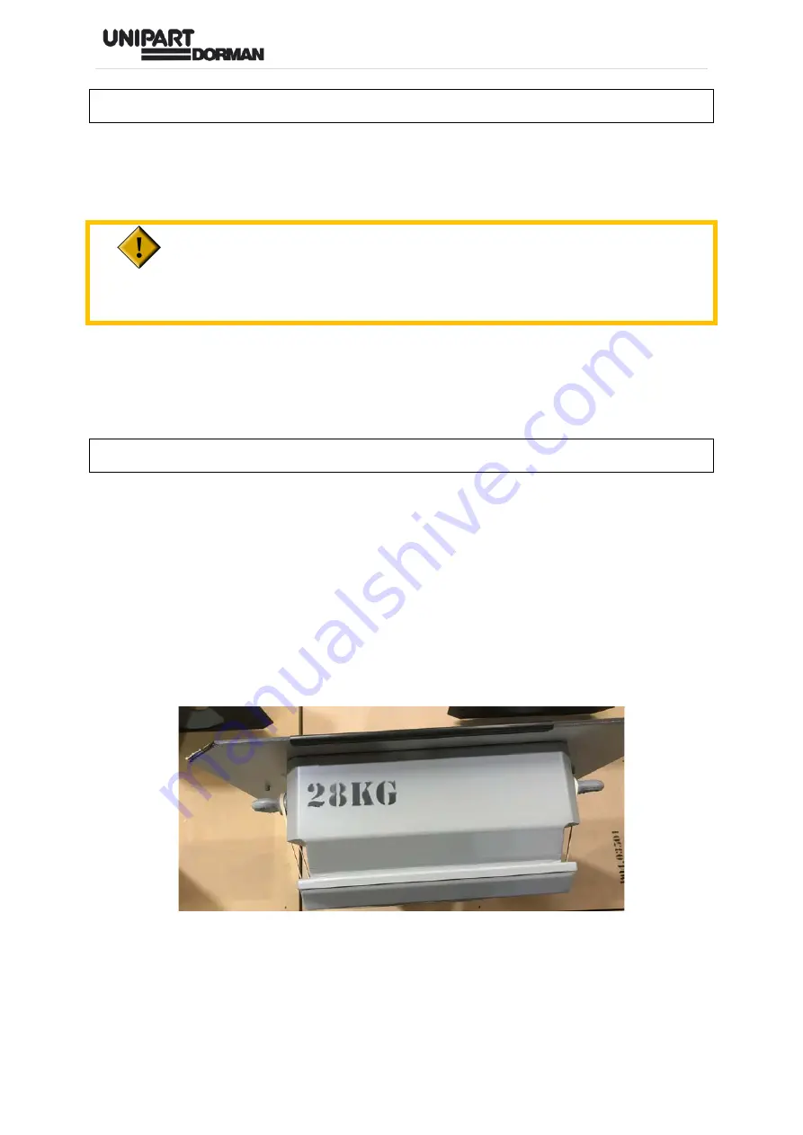
The gross weight of the signal is clearly marked on the top of the signal as shown 

and installers should ensure that they have sufficient measures in place to ensure a 

safe lift. 


All activity on the CLS LITE, both mechanical and electrical, must only be carried out 

by staff deemed competent in these fields by their employer. It is the user’s sole 

responsibility to ensure that the CLS  LITE  is installed and/or maintained by 

certificated and competent staff.   


Summary of Contents for CLS LITE

Page 1: ...INTELLIGENT ENGINEERING UNIQUE PEOPLE WORKING TOGETHER CLS LITE Operation Maintenance Manual C64 65201 Issue 3 June 2019...

Page 2: ...gnal Head 9 Backboard Arrangement 9 Signal Alignment 11 INSTALLATION AND ALIGNMENT OF CLS LITE HEADS USING THE UNIPART DORMAN ASSISTED LIFT TRUNNION 18 Preparing and Mounting the Signal Head 20 Backbo...

Page 3: ...cument that warrant extra vigilance the following two alert formats are used Activities identified as needing extra care are highlighted using the Caution Symbol ACTIVITIES WHICH ARE OR HAVE THE POTEN...

Page 4: ...drawing just 45mA is available giving a consumption of just 5 Watts A low current 24Vdc signal head may also be specified please contact Unipart Dorman for more information on these energy saving opt...

Page 5: ...is manual Safety Before commencing assembly any local safety requirements affecting the continued safe working environment of the signalling installation and or the working railway either directly or...

Page 6: ...al for lifting during installation This is covered in the Module Replacement section of this document BEFORE THE COMMENCEMENT OF ANY ACTIVITY ARRANGEMENTS SHALL BE APPLIED TO PROTECT THE WORKING RAILW...

Page 7: ...read in conjunction with the ALT Operations and Maintenance Manual C64 65976 which is available on the Unipart Dorman website Detachable Alignment Scope The Unipart Dorman Detachable Alignment Scope...

Page 8: ...there is no grit etc on the lens and then using a lint free cloth moistened with the water detergent solution carefully wipe the lens clean before using a dry second cloth to remove any water spotting...

Page 9: ...8 C64 65201 Issue 3 Jun 2019 INSTALLATION AND ALIGNMENT OF CLS LITE HEADS ON ALL STRUCTURES EXCEPT THE UNIPART DORMAN ASSISTED LIFT TRUNNION...

Page 10: ...nd a method of lifting the head into place shall be determined Two removable lifting rings are fitted to assist in mechanical lifting Once in the required position the CLS LITE is secured to the base...

Page 11: ...d the signal will not meet the 300mm backboard criterion Remove the Lower Backboard Extension from its stowage position above the aperture by removing the two 3mm Allen screws shown in blue below Refi...

Page 12: ...IGNAL IN STRICT ADHERENCE TO THE SIGNAL SIGHTING FORM REQUIREMENTS The Signal Sighting Form SSF will provide the definitive signal specific alignment details and should always be consulted prior to co...

Page 13: ...unit This Method is not to be used for signal heads mounted on the Unipart Dorman Spigot Mount fitted into the GRP Post and installed in the ALT Instructions for this mounting method are contained in...

Page 14: ...Issue 3 Jun 2019 4 Aspect and 3 Aspect tall Housings Use the threaded inserts in the inside of the frame in the positions shown below which correspond with the door stay mounting on the opposite side...

Page 15: ...the spacer is moved from its normal operating position Once the alignment procedure is complete refit the module spacer to the pivot bar with the flange end closest to the module They are a snap fit a...

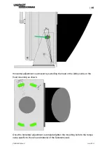
Page 16: ...hanged Detailed instructions on swapping the door are in a later section of this document Vertical adjustment of the head s tilt angle is carried out by loosening the bolt on either side of the basepl...

Page 17: ...adjustment is achieved by swivelling the head in the kidney slots on the fixed mounting as shown Once the horizontal adjustment is complete tighten the mounting bolts to the torque value specific to t...

Page 18: ...of use and instructions Unipart Dorman cannot accept any responsibility for the performance of third party equipment applications or software systems Users of these devices and their supporting opera...

Page 19: ...18 C64 65201 Issue 3 Jun 2019 INSTALLATION AND ALIGNMENT OF CLS LITE HEADS USING THE UNIPART DORMAN ASSISTED LIFT TRUNNION...

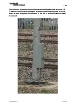
Page 20: ...he following instructions are unique to the Unipart Dorman Assisted Lift Trunnion which is easily identified by the use of a single connection cover and a circular baseplate Installation of the ALT is...

Page 21: ...cture to enable signal alignment from ground level Where the head is to be fitted to the GRP Post and ALT it will arrive upright on a pallet secured to a special to type mount To remove it from the Pa...

Page 22: ...PALLET CAREFULLY To install the spigot first slide the collar onto the post Insert the post cable up through the bore of the spigot and connect the plug coupler Fit the head into the post and ensure...

Page 23: ...gement section below The installation is now exactly the same as the procedure followed for a GRP Head and Post installed in an Assisted Lift Trunnion as shown in the ALT Operations and Maintenance Ma...

Page 24: ...entre of the lit aspect and the following procedure is applicable to both mounting arrangements To prevent damage to the lower portion of backboard during transit a removable section is fitted in a st...

Page 25: ...sing the existing Allen screws shown in green below mount the plate at the bottom of the backboard Correctly fitted backboard on a 3 aspect short housing signal head shown 3 aspect tall and 4 aspect s...

Page 26: ...lignment activity to be done using the ALT mount as described below and to ensure accuracy the signal shall be aligned to a point on the ground determined by the signal sighting form The illustration...

Page 27: ...ment scope to provide visual cues the signal is adjusted horizontally by rotating the base within the kidney slots and vertically by adjusting the angle of the ALT using the securing and adjustment nu...

Page 28: ...tive case If required the adaptor plate and camera described in the Detachable Signal Alignment Scope section above can be fitted INSTRUCTIONS COMMON TO BOTH VARIANTS Electrical Connection To reduce t...

Page 29: ...is is simply the preference of the manufacturer and does not affect the plug coupler s physical attributes The Plug Couplers should connect easily and the use of handtools is discouraged If the couple...

Page 30: ...e 3 Jun 2019 in the door bracket as shown This stowage option can also be used where the feed cable is fitted with a blanking cap The RYG Plug Couplers are stowed in their brackets in the positions sh...

Page 31: ...igned to be fitted so it hinges on the left or right to improve access to the signal Alignment scope The instructions below are illustrated using a 4 aspect head but the procedure is also the same for...

Page 32: ...reset on the manufacturing jig Door Preparation Note the assembly order of any fasteners removed in the instructions below to ensure correct re assembly sequence Undo the two dome nuts securing the d...

Page 33: ...bber doorstops shown in red fitted inside the door flange and retain Remove the hinge plates and then using the same dome nuts and washers reposition the hinges to the opposite side of the door fittin...

Page 34: ...the frame shown in blue above Move the two hinges to the opposite side of the frame Do not tighten at this stage to allow later door frame alignment 3 Aspect Short Housings Only Remove the adaptor blo...

Page 35: ...et assembly over and refit to the opposite side and attach the bonding lead Ensure all of the fasteners disturbed are torque loaded to 1 5 Nm The door is closed and secured using the locking bolt and...

Page 36: ...ist of signal heads spares and their catalogue numbers are shown on the Network Rail Approval Certificate Module Replacement Before replacing the module remove any cable ties and disconnect the plug c...

Page 37: ...36 C64 65201 Issue 3 Jun 2019 The module can then be swung out and if required is unhooked from the top bar for removal...

Page 38: ...AWAY FROM THE FRAME IT SHOULD NOT MOVE Ensure the plug couplers are stowed correctly in the support brackets and any cable ties are replaced If the module is simply to be tilted back to facilitate cle...

Page 39: ...reserve the right to modify designs and specifications whenever necessary The content of this document is the property of Unipart Dorman and information contained therein is confidential This document...

Reviews: