Unimig RAZOR COMPACT 250 Operating Manual Download Page 4

4

RAZOR COMPACT 250 

OPERATING MANUAL

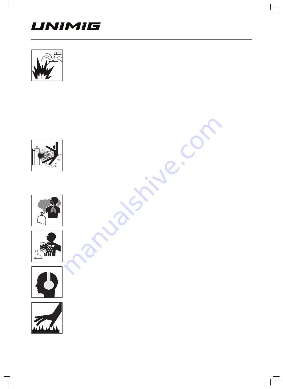
Fire hazard

•  Welding/cutting on closed containers, such as tanks, drums, or pipes, can cause them to explode. Flying sparks from the 

welding/cutting arc, hot workpiece, and hot equipment can cause fires and burns. Accidental contact of the electrode 
to metal objects can cause sparks, explosion, overheating, or fire. Check and be sure the area is safe before doing any 
welding/cutting.

•  The welding/cutting sparks & spatter may cause fire, therefore remove any flammable materials well away from the working 

area. Cover flammable materials and containers with approved covers if unable to be moved from the welding/cutting area.

•  Do not weld/cut on closed containers such as tanks, drums, or pipes, unless they are correctly prepared according to the 

required Safety Standards to ensure that flammable or toxic vapours and substances are totally removed, these can cause 
an explosion even though the vessel has been “cleaned”. Vent hollow castings or containers before heating, cutting or 
welding. They may explode.

•  Do not weld/cut where the atmosphere may contain flammable dust, gas, or liquid vapours (such as petrol)
•  Have a fire extinguisher nearby and know how to use it. Be alert that welding/cutting sparks and hot materials from welding/

cutting can easily go through small cracks and openings to adjacent areas. Be aware that welding/cutting on a ceiling, floor, 
bulkhead, or partition can cause a fire on the hidden side.

Gas cylinders

•  Shielding gas cylinders contain gas under high pressure. If damaged, a cylinder can explode. Because gas cylinders usually 

are part of the welding/cutting process, be sure to treat them carefully. CYLINDERS can explode if damaged.

•  Protect gas cylinders from excessive heat, mechanical shocks, physical damage, slag, open flames, sparks, and arcs.
•  Ensure cylinders are held secure and upright to prevent tipping or falling over.
•  Never allow the welding/cutting electrode or earth clamp to touch the gas cylinder, do not drape welding cables over the cylinder.
•  Never weld/cut on a pressurised gas cylinder, it will explode and kill you.
•  Open the cylinder valve slowly and turn your face away from the cylinder outlet valve and gas regulator.

Gas build-up

•  The build-up of gas can cause a toxic environment, deplete the oxygen content in the air resulting in death or injury. Many 

gases use in welding/cutting are invisible and odourless.

•  Shut off shielding gas supply when not in use.
•  Always ventilate confined spaces or use approved air-supplied respirator.

Electronic magnetic fields

•  MAGNETIC FIELDS can affect Implanted Medical Devices.
•  Wearers of Pacemakers and other Implanted Medical Devices should keep away.
•  Implanted Medical Device wearers should consult their doctor and the device manufacturer before going near any electric 

welding, cutting or heating operation.

Noise can damage hearing

•  Noise from some processes or equipment can damage hearing.
•  Wear approved ear protection if noise level is high.

Hot parts

•  Items being welded/cut generate and hold high heat and can cause severe burns.
•  Do not touch hot parts with bare hands. Allow a cooling period before working on the welding/cutting gun. Use insulated 

welding gloves and clothing to handle hot parts and prevent burns.

RAZOR Compact 250 Manual APR23.indd   4

RAZOR Compact 250 Manual APR23.indd   4

6/04/2023   4:02:58 PM

6/04/2023   4:02:58 PM

Summary of Contents for RAZOR COMPACT 250

Page 1: ...COMPACT250 U11010K Operating Manual RAZOR Compact 250 Manual APR23 indd 1 RAZOR Compact 250 Manual APR23 indd 1 6 04 2023 4 02 58 PM 6 04 2023 4 02 58 PM...

Page 2: ...6 9 MIG Manual Mode 17 10 Synergic Mode 17 11 MIG Machine Setup 18 12 MIG Welding Further Explained 25 13 TIG Machine Setup 32 14 TIG Welding Guide 36 15 MMA Machine Setup 40 16 MMA Welding Guide 43 1...

Page 3: ...and tear replace the cable immediately if damaged bare wiring is dangerous and can kill Do not use damaged undersized or badly joined cables Do not drape cables over your body We recommend RCD safety...

Page 4: ...sually are part of the welding cutting process be sure to treat them carefully CYLINDERS can explode if damaged Protect gas cylinders from excessive heat mechanical shocks physical damage slag open fl...

Page 5: ...uipment The machine will be ready for use again when the internal temperature reaches a safe level Over Voltage Supply Regarding the power supply voltage range of the machine please refer to the Main...

Page 6: ...for an extended time period In this situation it is recommended to open the cylinder valve set the flow rate to 8 10 L min close the cylinder valve and check after a minimum of 15 minutes 5 If there...

Page 7: ...wide variety of welding projects with ease Whether you re working with mild steel stainless steel aluminium or flux cored wire our machine has got you covered 4 Geared Wire Drive Experience smooth an...

Page 8: ...1 2mm U GROOVE 30 22 3 Package Contents RAZOR COMPACT 250 4m Electrode Holder 4m 300 AMP Earth Clamp Twin Gauge Argon Regulator Drive Roller 15A Plug Fitted 4m M24 Digital MIG Torch RAZOR Compact 250...

Page 9: ...1 12mm TIG Specifications TIG Function Type DC Lift Arc TIG Welding Current Range 5 250A TIG Duty Cycle 40 C 20 250A 60 144A 100 112A TIG Welding Thickness Range 1 10mm STICK Specifications STICK Weld...

Page 10: ...ort 5 Wired Remote Connection Port 6 Polarity Cable 7 Wireless Remote Indicator 5 2 Rear Panel Layout 8 On Off Switch 9 Gas Input 10 Input Power Cord 11 Gas Bottle Mounting Base 12 Gas Bottle Chain Mo...

Page 11: ...out 1 4 Geared Wire Drive System 2 Wire Spool Holder 3 Drive Roller Storage 4 Lift Handle 5 Cabinet Light 6 Settings Guide 1 2 5 6 4 3 RAZOR Compact 250 Manual APR23 indd 11 RAZOR Compact 250 Manual A...

Page 12: ...re Drive System 1 Drive Roller Assemblies 2 Upper Roller Assembly 3 Tensioner Knob 4 Guide Tube 5 Wire Inlet Guide Tube 1 1 2 3 5 4 RAZOR Compact 250 Manual APR23 indd 12 RAZOR Compact 250 Manual APR2...

Page 13: ...tton 6 Material Gas Selection Buttons 7 Wire Diameter Size Selection Button 8 Torch Mode Selection Button 9 MIG Mode Button 10 Remote Mode Button 11 Synergic Mode Button 12 Wire Feed Button 13 Gas Tes...

Page 14: ...ne s default is MIG manual mode For Synergic mode press the Synergic Mode Button located on the front panel MMA Stick Mode This indicates that the machine is in Manual Metal Arc mode For MIG Synergic...

Page 15: ...thickness or wire speed You can also fine tune the recommended settings Wire Feed Press this button to activate the drive rollers This allows for easy and safe wire feeding when changing out rolls of...

Page 16: ...of the different settings is indicated by a code Standby Timer Input Over Voltage Protection Pre Flow Air Timer MIG Post Flow Air Timer MIG Pre Flow Air Timer TIG Post Flow Air Timer TIG Downslope Ti...

Page 17: ...voltage by default as well as Inductance and Burnback by pressing the knob in Note Available adjustment voltage with Knob B is based on your settings with Knob A Adjustment Knob B will adjust your vol...

Page 18: ...anti clockwise Then pull it towards you so that the knob clears the upper roller assembly 4 You now have access to the drive rollers When re installing your desired drive rollers ensure you line up th...

Page 19: ...and the earth clamp into the dinse port DCEN is used primarily for gasless flux cored welding 7 With the polarity cable and the earth clamp installed into the correct dinse ports now install the MIG...

Page 20: ...nut clockwise to loosen 10 With the spool holder retainer nut removed slide the spool onto the spool holder Ensure you line up the key hole on the spool with the key on the base of the spool holder 11...

Page 21: ...knob locked in place twist the tensioner knob to give the wire a medium amount of tension This may need to be adjusted later 15 Connect the plug into a power point then switch the machine ON 16 Prepar...

Page 22: ...st the gas nozzle 19 Check the tension by pinching the sides of the wire past the tip of the torch while wearing a glove Feed the wire while applying light pressure with your fingers You want the tens...

Page 23: ...supplied gas hose to the outlet port of the regulator 21 Tighten securely with wrench 23 Plug the quick connect end of the gas hose to the port on the back of the machine FOR FLUX CORED GASLESS WIRE S...

Page 24: ...MIG mode selected using the WELD MODE button 25 Connect earth clamp to your workpiece 27 Line up the torch with your workpiece then pull the trigger to initiate the weld For gas shielded MIG the push...

Page 25: ...parates from the end of the wire and forms a droplet that is transferred into the weld pool This process is repeated about 100 times per second making the arc appear constant to the human eye Short Ci...

Page 26: ...Push Technique The wire is located at the leading edge of the weld pool and pushed towards the un melted work surface This technique offers a better view of the weld joint and direction of the wire in...

Page 27: ...ideal and produces the right level of control over the weld pool A travel angle higher than 20 will give an unstable arc condition with poor weld metal transfer less penetration high levels of spatter...

Page 28: ...joint penetration Lack of fusion Porosity Cold lap Large wide bead Travel Speed Too Slow Correct Travel Speed Good penetration Good toe fusion Even shaped bead Good sidewall fusion Gas Selection The p...

Page 29: ...more suited for this Aluminium U Groove Aluminium requires a U shape groove Aluminium wire has a lot less column strength can bend easily and is therefore more difficult to feed Soft wires can easily...

Page 30: ...TA Cooling Method Air Cooled Duty Cycle CO2 60 250A Duty Cycle MIxed Gas 60 220A Wire Size 0 8 1 2mm Standard EN60974 7 TORCH LENGTHS Length 3m 4m SKU U41010 U41011 RAZOR Compact 250 Manual APR23 indd...

Page 31: ...nium SKU DESCRIPTION QTY U41013 M24 Torch Swan Neck 1 SKU DESCRIPTION QTY PCT0009 06 CONTACT TIPS Steel 0 6mm 10 PCT0009 08 CONTACT TIPS Steel 0 8mm 10 PCT0009 09 CONTACT TIPS Steel 0 9mm 10 PCT0009 1...

Page 32: ...torch correctly lined up and pressed inwards twist the locking nut to finish the torch installation 4 After connecting the torch and polarity cable plug the earth clamp into the dinse port and twist i...

Page 33: ...flowmeter regulator into your gas outlet 7 Connect gas hose to the flowmeter outlet using the twist nut to tighten the fitting securely 8 Connect the other end of the gas hose to the gas inlet on the...

Page 34: ...g into a power point then switch the machine ON 11 Select TIG mode using the WELD MODE button located on the front panel Then input your desired settings for amperage 12 Connect earth clamp to your wo...

Page 35: ...on the torch to initiate the gas flow 14 Touch the tip of the tungsten to the workpiece 15 Lift the torch up slightly to initiate the arc RAZOR Compact 250 Manual APR23 indd 35 RAZOR Compact 250 Manua...

Page 36: ...r regulates the welding current to adjust the power of the arc Typically thin material requires a less powerful arc with less heat to melt the material so less current amps is required Thicker materia...

Page 37: ...ld pool of the desired size Once the weld pool is established tilt the torch at about a 75 angle and move smoothly and evenly along the joint while fusing the materials together TIG Welding with Fille...

Page 38: ...occur and the more difficult it will be to arc start However increasing the flat to the maximum level that still allows arc starts and eliminates arc wander will improve the weld penetration and incr...

Page 39: ...only individual results may vary depending on technique skill and material TIG Tungsten Selection Guide Tungsten Electrodes Rating for Welding Currents Tungsten Diameter mm Diameter at the Tip mm Cons...

Page 40: ...clamp to the dinse connection and electrode holder to the dinse connection 3 Connect the plug into a power point then switch the machine ON 4 Ensure that MMA mode is activated on the front panel by pr...

Page 41: ...n grip 6 Place electrode into electrode holder 7 Twist electrode holder to tighten and securely grip electrode 8 Connect earth clamp to your workpiece RAZOR Compact 250 Manual APR23 indd 41 RAZOR Comp...

Page 42: ...ctrode to the workpiece to initiate arc 10 Drag along workpiece to weld Pull the electrode away from the workpiece to finish weld RAZOR Compact 250 Manual APR23 indd 42 RAZOR Compact 250 Manual APR23...

Page 43: ...om the electrode coating The arc and the immediate area are enveloped by an atmosphere of protective gas Manual Metal Arc stick electrodes have a solid metal wire core and a flux coating These electro...

Page 44: ...welds The general rule of thumb for down hand welding is to have an arc length no greater than the diameter of the core wire Electrode Angle The angle that the electrode makes with the work is importa...

Page 45: ...ase oil and dirt including mill scale from base metal Contaminated MIG wire Use clean dry rust free wire Do not lubricate the wire with oil grease etc Gas nozzle clogged with spatter worn or out of sh...

Page 46: ...orch lead too long Small diameter wires and soft wires like aluminium don t feed well through long torch leads replace the torch with a shorter length torch MIG torch lead kinked or too sharp angle be...

Page 47: ...Porosity Poor weld appearance and colour Wrong gas poor gas flow gas leaks Use pure argon Gas is connected check hoses gas valve and torch are not restricted Set the gas flow between 8 12 L min Check...

Page 48: ...se connection Check all connectors and tighten Earth clamp not connected to work Connect the earth clamp directly to the workpiece wherever possible 19 MMA STICK Troubleshooting 1 No arc Incomplete we...

Page 49: ...pearance Unsteady hand wavering hand Use two hands where possible to steady up practise your technique 8 Distortion Movement of base metal during welding Excessive heat input Reduce the amperage or us...

Page 50: ...o turn off RED VRD ICON Abnormal VRD The No Load voltage is too high This is likely caused by VRD fault Possible Solution Power down and restart machine THERMAL OVERLOAD OVERCURRENT LIMIT VRD NORMAL A...

Page 51: ...51 RAZOR COMPACT 250 OPERATING MANUAL 23 Wiring Diagrams RAZOR Compact 250 Manual APR23 indd 51 RAZOR Compact 250 Manual APR23 indd 51 6 04 2023 4 03 16 PM 6 04 2023 4 03 16 PM...

Page 52: ...52 RAZOR COMPACT 250 OPERATING MANUAL 24 Machine Breakdown and Parts List RAZOR Compact 250 Manual APR23 indd 52 RAZOR Compact 250 Manual APR23 indd 52 6 04 2023 4 03 19 PM 6 04 2023 4 03 19 PM...

Page 53: ...01118 Valve 31 10004818 Power Cable Code Name 32 51003429 Large Cable Clip 33 10084286 Knob Switch 34 51001733 Windshield 35 51001088 EMC Board 36 51001148 Control Board 37 51001143 Power Supply Board...

Page 54: ...54 RAZOR COMPACT 250 OPERATING MANUAL Notes RAZOR Compact 250 Manual APR23 indd 54 RAZOR Compact 250 Manual APR23 indd 54 6 04 2023 4 03 19 PM 6 04 2023 4 03 19 PM...

Page 55: ...55 RAZOR COMPACT 250 OPERATING MANUAL Notes RAZOR Compact 250 Manual APR23 indd 55 RAZOR Compact 250 Manual APR23 indd 55 6 04 2023 4 03 19 PM 6 04 2023 4 03 19 PM...

Page 56: ...3274 5829 EMAIL qld unimig com au VIC OFFICE 91 Yellowbox Drive Craigieburn VIC 3064 PH 03 8682 9911 FAX 03 9333 7867 EMAIL sales unimig com au WA OFFICE 26 Sustainable Ave Bibra Lake WA 6163 PH 08 63...

Reviews: