


PART II: OPERATION
19
OPERATION
Turn the switch A on the burner control panel to the ON position.
Check the control box is not locked (LED B on), in this case press the reset button accessible from the upper side of the electrical
board (see next picture) or the pushbutton C on the frontal panel of the electrical board.
Check the thermostats (or pressure switches) enable the burner to operate.
The burner start up cycle begins: the contrl box activates the burner fan and meanwhile the ignition transformer (signalled by the
light H on the front panel); pre-purgephase lasts some seconds according to the control box type provided with the burner.
At the end of pre-purgue time, the first stage solenoid valve EV1 is energised, indicated by the LED D on the display panel and the
burner lights.
The ignition transformer remains on for some seconds after the flame is lit (post ignition time), after this time it is cut out and the
light H tunrs off.
The burner is on in the low flame stage (led G on); after 5 - 15 sec. (according to the control box type), it goes into the two-stage
mode and turns automatically to high flame or remains in low flame, according to the system demands. High or low flame opera-
tion is shown by the light F (high flame) or light G (low flame). The light E is on when the solenoid valve of the high flame is open,
feeding the nozzle of the second stage.
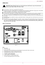
Burner control panel
Keys
A
Main switch
B
Burner lockout light
C
Reset button for flame control device (only burners fitted with remote reset for flame control device)
D
Signalling light of the opening of 1st stage solenoid valve
E
Signalling light of the opening of 2nd stage solenoid valve
F
High flame operation signalling light
G
Low flame operation signalling light
H
Ignition transformer in operation signalling light
I
Overload tripped signalling light ( PG30 excluded)
ATTENTION:
before starting the burner up, be sure that the manual cutoff valves are open. Be sure themains
switch is closed. Read carefully th “Warnings” chapter.
Fig. 10
F
G
H
I
B
E
D
C
A