Unigas RG91 Manual Of Installation - Use - Maintenance Download Page 12

PART II: INSTALLATION

12

Bleed

Bleeding in two-pipe operation is automatic : it is assured by a bleed flat on the piston. In one-pipe operation, the plug of a pressure
gauge port must be loosened until the air is evacuated from the system.

About the use of fuel pumps

Make sure that the by-pass plug is not used in a single pipe installation, because the fuel unit will not function properly and damage
to the pump and burner motor could result.

Do not use fuel with additives to avoid the possible formation over time of compounds which may deposit between the gear teeth,
thus obstructing them.

After filling the tank, wait before starting the burner. This will give any suspended impurities time to deposit on the bottom of the
tank, thus avoiding the possibility that they might be sucked into the pump.

On initial commissioning a "dry" operation is foreseen for a considerable length of time (for example, when there is a long suction
line to bleed). To avoid damages inject some lubrication oil into the vacuum inlet.

Care must be taken when installing the pump not to force the pump shaft along its axis or laterally to avoid excessive wear on the
joint, noise and overloading the gears.

Pipes should not contain air pockets. Rapid attachment joint should therefore be avoided and threaded or mechanical seal jun-
ctions preferred. Junction threads, elbow joints and couplings should be sealed with removable sg component. The number of jun-
ctions should be kept to a minimum as they are a possible source of leakage.

Do not use PTFE tape on the suction and return line pipes to avoid the possibility that particles enter circulation. These could depo-
sit on the pump filter or the nozzle, reducing efficiency. Always use O-Rings or mechanical seal (copper or aluminium gaskets) jun-
ctions if possible.

An external filter should always be installed in the suction line upstream of the fuel unit.
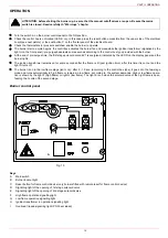
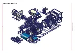
Light oil pumps

Key

1  Pressure governor
2  Pressure gauge
3  Vacuum gauge
5  Nozzle
7  Suction
8  Return


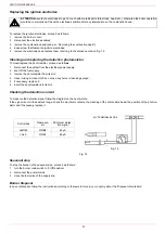
Connecting the oil flexible hoses to the pump

To connect the flexible oil hoses to the pump, proceed as follows, according to the pump provided:
1

remove the closing nuts A and R on the inlet and return connections of the pump;

2

screw the rotating nut of the two flexible hoses on the pump 

being careful to avoid exchanging the lines

: see the arrows marked

on the pump.

For further information, refer to the technical documentation of the pump.

Suntec J6 - J7

Oil viscosity

2.8 - 200 cSt

Oil temperature

0 - 90°C

Min. suction pressure

- 0,45 barto avoid gasing

Max. suction pressure

1.5 bar

Max. return pressure

1.5 bar 

Rotation speed

3600 rpm max.

Suntec J6-J7

R

A

Summary of Contents for RG91

Page 1: ...RG91 RG92 M039192CB Rev 4 0 10 2020 BURNERS BRUCIATORI BRULERS BRENNER QUEMADORES Light oil burners Double Stage MANUAL OF INSTALLATION USE MAINTENANCE...

Page 2: ...e employed exclusively for the use for which it was designed Before connecting the burner make sure that the unit rating is the same as delivery mains electricity gas oil or other fuel Observe caution...

Page 3: ...gaseous fuels 2014 35 UE Low Tension Directive 2014 30 UE Electromagnetic compatibility Directive 2006 42 EC Machinery Directive Harmonized standards UNI EN 676 Automatic forced draught burners for ga...

Page 4: ...s oil and solid fuel burning appliances having electrical connections UNI EN ISO 12100 2010 Safety of machinery General principles for design Risk assessment and risk reduction National Standard UNI 7...

Page 5: ...rner is suitable if the intersection point A is inside the performance curve Fig 4 Data are referred to standard conditions atmospheric pressure at 1013mbar ambient temperature at 15 C Burner model id...

Page 6: ...AX position see paragraph Adjusting the combustion head the minimum output point is rea ched setting the combustion head to its MIN position During the first ignition the combustion head is set in ord...

Page 7: ...blast tube provided A AS A AL AA AB AC AD AE B BS B BL C CC E F G H K L M N Omin Omax P T W Y Z RG91 1144 1317 242 182 256 35 367 300 473 844 422 419 434 238 268 360 464 M12 417 280 310 295 80 649 228...

Page 8: ...ary use a spray adhesive on the flange 5 install the burner into the boiler 6 fix the burner to the stud bolts by means of the fixing nuts according to the picture below 7 After fitting the burner to...

Page 9: ...t tube lenght follow the instructions of the boiler manufacturer In absence of these consider the following Cast iron boilers three pass flue boilers with the first pass in the rear part the blast tub...

Page 10: ...filter 3 Light oil feeding pump 4 One way valve 5 Flexible hoses 6 Relief valve NOTE in plants where gravity or ring feed systems are provided install an automatic interception device RING CIRCUIT GR...

Page 11: ...the pump Burners come out from the factory provided for double stage systems They can be suited for single pipe system recommended in the case of gravity feed as decribed before The bypass plug insert...

Page 12: ...s Rapid attachment joint should therefore be avoided and threaded or mechanical seal jun ctions preferred Junction threads elbow joints and couplings should be sealed with removable sg component The n...

Page 13: ...earth terminal RC466890660 For LMV5 control box please refer to the clabeling recommendations avaible on the Siemens CD attached to the burner WARNING only for double stage and progressive burners Th...

Page 14: ...would cause the pump seal to break ATTENTION During commissioning operations do not let the burner operate with insufficient air flow danger of formation of carbon monoxide if this should happen make...

Page 15: ...00 15 00 200 2 042 000 2374 30 00 22 00 28 00 20 00 28 00 16 00 205 2 093 050 2434 32 00 22 00 30 00 20 00 28 00 17 00 210 2 144 100 2493 32 00 24 00 32 00 19 00 28 00 18 00 G P H PUMP PRESSURE bar 1...

Page 16: ...erger STA6 this actuator is not provided with the manual control of the air damper The adjustment of the cams is carried out by means of the cam lever Siemens SQN72 a key is provided to move cams I an...

Page 17: ...sition 18 Once the adjustmet is performed check again that the combustion parameters are in the set limits 19 Replace the actuator cover Adjusting the combustion head To let the burner operate at a lo...

Page 18: ...ND SAFE FUNCTIONING OF THE BURNER THEREFORE ANY OPERATION OF THE APPLIANCE MUST BE PREVENTED WHICH DEPARTS FROM THE INSTALLATION OPERATIONS OR WHICH HAPPENS AFTER TOTAL OR PARTIAL TAMPERING WITH THESE...

Page 19: ...out and the light H tunrs off The burner is on in the low flame stage led G on after 5 15 sec according to the control box type it goes into the two stage mode and turns automatically to high flame o...

Page 20: ...rease levers and rotating parts 1 Close the bowl valve before the self cleaning filter 2 Switch off any electrical equipment on board on the filter example motorization or heaters 3 Disconnect the out...

Page 21: ...e sure to tight the screw on the electrodes group before reassembling the combustion head Fig 12 Fig 11 ATTENTION avoid the electrodes to get in touch with metallic parts blast tube head etc otherwise...

Page 22: ...hecking the detection current To measure the detection signal follow the diagram on the next picture If the signal is not in the advised range check the electrical contacts the cleaning of the combust...

Page 23: ...RNER DOESN T SWITCH TO HIGH FLAME THE BURNER STOPS DURING OPERATION THE BURNER STOPS AND REPEATS THE CYCLE DURING OPE RATION MAIN SWITCH OPEN LINE FUSE INTERVENTION MAX PRESSURE SWITCH FAULT FAN THERM...

Page 24: ...RNER EXPLODED VIEW C B C B 14 13 1 8 1 1 7 1 5 16 1 1 1 1 1 1 4 1 8 8 2 1 2 1 3 8 1 6 18 1 8 2 4 1 4 3 4 2 4 4 15 2 1 10 7 10 3 10 2 10 1 10 5 10 4 9 1 9 2 7 1 7 1 7 3 3 5 3 6 3 2 3 3 3 4 3 6 2 2 11 1...

Page 25: ...AIR INTAKE DAMPER 9 2 CONTROL BOX 1 8 1 AIR DAMPER SILENCER 10 1 LIGHT 1 8 2 AIR DAMPER INDEX 10 2 LIGHT 2 1 FAN WHEEL 10 3 SWITCH 2 2 MOTOR 10 4 LOCK OUT RESET BUTTON 3 1 COMBUSTION HEAD 10 5 PROTECT...

Page 26: ......

Page 27: ......

Page 28: ...a L Galvani 9 35011 Campodarsego PD ITALY Tel 39 049 9200944 Fax 39 049 9200945 9201269 web site www cibunigas it e mail cibunigas cibunigas it Note specifications and data subject to change Errors an...

Page 29: ...FR...

Page 30: ......

Reviews: