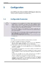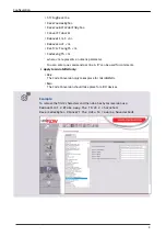
▪ {number}: 1,2,3,... up to 16. Do not use a leading 0, i.e. do not use RULE01, RULE02 …
▪
but instead RULE1, RULE2 …
▪ {product}: product index which is used for click counting if the rule matches. The
▪
product index is calculated directly as mask&x if the value is set to -1, where x is the
data word on the I/O port and "&" denotes the binary AND operator. The data bits in
x may occur reversed or inverted or both if configured as explained under [PORTS]
above.
▪ {mask}, {pattern}: The rule match condition holds true if mask&x = pattern, where x is
▪
the data word on the I/O port. Again, "&" denotes the binary AND operator. The data
bits in x may be reversed or inverted or both if configured as explained under [PORTS]
above.
▪ {counter}: For multi-clicks, the assignment of a counter index is required. The counter
▪
index may be within 0 and 15 and if not used set to -1. The counters are shared
between all [DIPORTn] sections.
▪ {clicks}: set to 0 if multi-clicks are not used, otherwise give the number of clicks for
▪
this match to hold true.
Note that the numerical values in the rules (and only in the rules, not elsewhere) can
be entered either in decimal (e.g. 17), binary (b10001), octal (o21) or hexadecimal
(0xd1 or $D1) format. Comments can be started after the {clicks} value with any non-
whitespace character, for example '#' or ';'.
Examples of rules for the Canon Interface Kit A1/A2 (see
18) are provided below.
Canon Signal Kit A1/A2
This Signal Kit A1 uses the information of the CCM3-COIN ROBO-bus of the CL resp. B/W
controller to generate or accept the following signals on its connector J2:
▪ PIN 1: delivery 1: generated at the time of paper delivery - all other signals are only
▪
valid when this signal is set to 1.
▪ PIN 2: paper size - 0: small, 1: large
▪
▪ PIN 3: color - 0: B/W, 1: color
▪
▪ PIN 4: print - 0: copy, 1: print or fax
▪
▪ PIN 5 & 6: paper feeding position as follows:
▪
◦ 00: cassettes or internal paper decks (drawer 1-4)
◦
◦ 01: side paper deck (drawer 5)
◦
◦ 10: duplex tray
◦
◦ 11: stack bypass
◦
In binary representation, the bit order as seen by the MIND is "b54321" with the cable
between MIND and Kit soldered as in the cable schematics PDF. The bit mask b000010
for instance, matches PIN 2 – paper size.
Example PORT.INI for Signal Kit A1/A2
[PORT]
18
microMIND V2 Signal Interpreter and Configuration
8.2
Summary of Contents for microMIND V2
Page 1: ...microMIND V2 Installation Configuration Manual...
Page 2: ......
Page 10: ......
Page 14: ...microMIND V2 secure printing and copy accounting device locking 2 Introduction...
Page 25: ...About The About site shows legal information 13 microMIND V2 Website 6 4...
Page 26: ...14 microMIND V2 Website...
Page 34: ...microMIND V2 IO Connector 22 Specifications...
Page 42: ...NT ware 2009 2022...


