background image

OM-NGB    9

Operation

A.   Controls


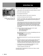
Operating controls are located on the front panel of the unit.

a.  

The on/off switch starts the unit or shuts it off.

b.  

The RESET indicator lights to show that the boiler has filled with water 

and that the main burners can ignite.

c.  

The start switch (momentary) lights the main burners. It also restarts 

the unit if electrical power is interrupted, or if a low water condition in 

the boiler disables the unit.

d. 

In addition to operating these controls, there are gas supply controls 

located on the gas valve.


For NGB-3E: 

When the control knob is “ON,” gas flows to the pilot, as


well as to the main burners.

B.   Operating Procedure

a.  

Turn on the water supply to the unit.

b.  

Turn on electrical power to the unit.

c.  

Turn on the gas supply to the unit, and turn on the gas valve.

Turn the control knob .on the gas valve to the “ON” position.


NOTE: The “ignition trial” period runs for approximately 90 seconds after the on/

off switch is turned ON. This means that if the pilot light does not light within 

the “trial” period, the ignition system will automatically stop the gas flow and 

terminate the ignition trial. If ignition is terminated, turn the switch off and then 

“ON” again to repeat the trial. Normally, the pilot should light within five seconds 

of turning on the unit.

d.  

Turn the on/off switch on the front of the cabinet to “ON.”

1)  

The amber light will come on.

2)  

The boiler drain valve will close and the unit will fill with water.

3)  

When the water reaches the “mid” probe, the red RESET light 

will come on.

4)  

Press the start switch.

5)  

The green light in the switch will come on, the RESET light will 

go off, and the main burner will light.

6)  

When the water level reaches the “hi” probe, the water supply 

to the boiler will shut off.

e.  

After about 15 minutes, the pressure gauge will indicate that the 

pressure is rising. When it reaches 9-1/2 PSI, the main burner will 

shut off. Thereafter, the burner will periodically relight to maintain 

the pressure at 9-1/2 PSI. The pilot light should stay lit when the 

burner is off.

f.  

To shut down the unit, turn the on/off switch to OFF. The unit will drain 

automatically after it has cooled to about 170ºF. The unit turns off the 

pilot light when the on/off switch is turned to OFF.

WARNING

ALL POTENTIAL USERS OF THE EQUIPMENT 

SHOULD BE TRAINED IN SAFE AND CORRECT 

OPERATING PROCEDURES.

Summary of Contents for Groen CNGB-24

Page 1: ...ING Improper installation adjustment alteration service or maintenance can cause property damage injury or death Read the installation operating and maintenance instructions thoroughly before installi...

Page 2: ...6 In addition please review the sales terms and conditions set forth below IMPORTANT NOTICE WARRANTIES LIMITATIONS ON WARRANTIES AND LIMITATION OF REMEDIES The following Warranties Limitation on Warra...

Page 3: ...NATIONAL FIRE PROTECTION ASSOCIATION 60 Batterymarch Park Quincy Massachusetts 02269 NFPA 70 The National Electrical Code NFPA 54 Installation of Gas Appliances Piping NFPA 96 Ventilating Hoods NSF I...

Page 4: ...he boiler is constructed of 1 4 thick steel which is certified by the American Society of Mechanical Engineers ASME for pressure vessels All welds are hydrostatically tested The boiler is also equippe...

Page 5: ...The water going to the steam generator should be within these guidelines WATER QUALITY REQUIREMENTS Containment Water Supply pH 7 to 9 Total Dissolved Solids TDS 30 to 60 ppm Hardness less than 60 pp...

Page 6: ...g system by closing its individual manual shut off valve during any pressure testing of the gas supply piping system at test pressures equal to or less than 1 2 PSI 3 45 kPA 1 Gas Supply Connection a...

Page 7: ...If it is over 60 PSI a pressure regulator is required A strainer screen at the connection is also recommended to trap any debris before it can enter the system c The boiler uses a maximum of 12 9 gal...

Page 8: ...o repeat the trial for ignition 5 Turn the on off switch on the cabinet front panel to the ON position The amber light in the switch will come on The boiler drain valve will close The unit will fill w...

Page 9: ...cally stop the gas flow and terminate the ignition trial If ignition is terminated turn the switch off and then ON again to repeat the trial Normally the pilot should light within five seconds of turn...

Page 10: ...ce the pressure has reached 9 1 2 PSI the main burner will be shut off by an operating pressure switch Residual heat stored in the boiler s heat exchanger can however cause the pressure to continue to...

Page 11: ...boiler The valve is located under the boiler 3 Close the manual drain valve 4 Turn off water supply to the boiler 5 Allow the boiler to cool This takes several hours so it is recommended that you cool...

Page 12: ...doors 19 Turn the on off switch OFF and slowly open the manual drain valve 20 When the boiler has drained completely close the manual drain valve and turn the on off switch to ON to fill the boiler w...

Page 13: ...ck of the following will help prevent down time and ensure continued efficient operation 1 Pressure gauge operation 2 Proper water level gauge 3 Strainer in water feed line clear 4 Air inlets for gas...

Page 14: ...an 60 PSI Authorized Service Rep Only c Is the Water Level Control Board defective Check for loose electrical connections on hi water fill solenoid X d Is the water fill solenoid valve defective X Che...

Page 15: ...ilds pressure but shuts down RESET light comes on User a Is the water level below the mid water level probe Verify that the water supply is sufficient to maintain the water level at or above the mid w...

Page 16: ...a Main Burner Assy 0 2000 Ft Elev Incl 29 Gas Jets W 54 Drill Dia Hole For Natural Gas 047267 7a Main Burner Assy 0 2000 Ft Elev Incl 29 Gas Jets W 68 Drill Dia Hole For Propane Gas 050491 8 Gas Valve...

Page 17: ...ssure Relief Valve 12PSI 099228 7 Water Level Probes lo med hi 076526 8 Solenoid Valve Water in 099220 9 Check Valve 004187 10 Air Vent 145167 11 Vacuum Breaker 090787 12 Globe Valve 1 2 NPT 099255 13...

Page 18: ...l Block 2 Pole 003887 Bushing Snap 11 16 ID 012864 7 Circuit Board Support 099292 8 Water Level Control Board Assembly 116016 9 Lug Ground 14 6 AWG 119829 10 Circuit Breaker 119860 11 Transformer 75VA...

Page 19: ...D 11 WHITE P1 J1 1 TSTAT DRAIN VALVE 1 2 2 T1 LO 14 5 PSI OPERATING PRESSURE GAS VALVE 7 YELLOW 8 BLACK C HL 12 BLACK 10 BLACK 9 RED C PS SW H C G BLACK YELLOW BLUE WHITE 4 BLACK 6 BROWN 5 BLUE 3 BROW...

Page 20: ...20 OM NGB Service Log Model No Purchased From Serial No Location Date Purchased Date Installed Purchase Order No For Service Call Date Maintenance Performed Performed By...

Reviews: