2 OM-NGB
IMPORTANT - READ FIRST - IMPORTANT
WARNING:
THE UNIT MUST BE INSTALLED BY PERSONNEL QUALIFIED
TO WORK WITH GAS, ELECTRICITY AND PLUMBING.
IMPROPER INSTALLATION CAN CAUSE INJURY TO
PERSONNEL AND/OR DAMAGE TO THE EQUIPMENT.
THE UNIT MUST BE INSTALLED IN ACCORDANCE WITH
APPLICABLE CODES.
NOTICE:
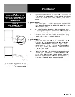
LEVEL THE UNIT BEFORE USE. IT MAY BE PITCHED
SLIGHTLY TO THE REAR.
CAUTION:
AN ELECTRICAL GROUND IS REQUIRED.
CAUTION:
DO NOT LOCATE THE BOILER CABINET DIRECTLY OVER A
FLOOR DRAIN OR FLOOR SINK. HUMIDITY OR WATER FROM
A DRAIN WILL DAMAGE ELECTRICAL PARTS OF THE UNIT.
WARNING:
TO AVOID DAMAGE OR INJURY, FOLLOW THE WIRING
DIAGRAM EXACTLY WHEN CONNECTING A UNIT.
CAUTION:
DO NOT USE PLASTIC PIPE. DRAIN MUST BE RATED FOR
STEAM AND BOILING WATER.
WARNING:
DO NOT CONNECT THE DRAIN DIRECTLY TO A BUILDING
DRAIN.
WARNING:
BLOCKING THE DRAIN MAY BE HAZARDOUS.
IMPORTANT:
IMPROPER DRAIN CONNECTION WILL VOID WARRANTY.
WARNING:
ALLOW COOKING CHAMBERS TO COOL BEFORE CLEANING.
WARNING:
CAREFULLY READ THE WARNINGS AND FOLLOW
THE DIRECTIONS ON THE LABEL OF EACH CLEANING
AGENT. USE SAFETY GLASSES AND RUBBER GLOVES AS
RECOMMENDED BY DELIMING AGENT MANUFACTURER.
WARNING:
DO NOT MIX DE-LIMING AGENTS (ACID) AND DE-GREASERS
(ALKALI) IN THE STEAM GENERATOR OR ON THE COOKING
CHAMBER WALLS.
NOTICE:
DO NOT USE A CLEANING OR DE-LIMING AGENT THAT
CONTAINS ANY SULFAMIC ACID OR ANY CHLORIDE,
INCLUDING HYDROCHLORIC ACID (HCL). IF THE CHLORIDE
CONTENT OF ANY PRODUCT IS UNCLEAR, CONSULT THE
MANUFACTURER.
NOTICE:
DO NOT USE A DE-GREASER THAT CONTAINS POTASSIUM
HYDROXIDE OR SODIUM HYDROXIDE OR THAT IS HIGHLY
ALKALINE.
WARNING:
USE OF ANY REPLACEMENT PARTS OTHER THAN THOSE
SUPPLIED BY THE MANUFACTURER OR THEIR AUTHORIZED
DISTRIBUTOR VOIDS ALL WARRANTIES AND CAN CAUSE
BODILY INJURY TO THE OPERATOR AND DAMAGE THE
EQUIPMENT. SERVICE PERFORMED BY OTHER THAN
FACTORY-AUTHORIZED PERSONNEL WILL VOID ALL
WARRANTIES.
WARNING:
HIGH VOLTAGE EXISTS INSIDE CONTROL COMPARTMENTS.
DISCONNECT POWER SOURCE BEFORE SERVICING.
FAILURE TO DO SO CAN RESULT IN SERIOUS INJURY OR
DEATH.
WARNING:
DO NOT EXPOSE SKIN TO ESCAPING STEAM. SEVERE
BURNS CAN RESULT.
CAUTION:
MAKING ANY ELECTRICAL OR MECHANICAL CHANGE IN
THE UNIT WITHOUT PRIOR WRITTEN APPROVAL FROM
ENGINEERING WILL VOID ALL WARRANTIES.
WARNING:
ALL POTENTIAL USERS OF THE EQUIPMENT SHOULD
BE TRAINED IN SAFE AND CORRECT OPERATING
PROCEDURES.
WARNING:
DO NOT OPERATE THE UNIT UNLESS ALL REMOVABLE
PANELS (RIGHT, LEFT, FRONT AND REAR) HAVE BEEN
PROPERLY INSTALLED.
WARRANTY
Congratulations on the purchase of your new Unified Brands equipment. We hope you
enjoy many years of reliable service in connection with the same. Please review all of
the important safety and operational information contained in the Operator’s Manual
for this equipment before it is placed in service. If you have any questions related to
equipment set up, operations, or service, please call 888-994-7636.
In addition, please review the sales terms and conditions set forth below.
*****IMPORTANT NOTICE*****
WARRANTIES, LIMITATIONS ON WARRANTIES, AND LIMITATION OF REMEDIES
The following Warranties, Limitation on Warranties, and Limitation of Remedies are
included in the terms of sale for this product. Please read this entire warranty and all
warranty modifications, disclaimers, and limitations of remedies set forth herein before
accepting or using this equipment or product. Customer acknowledges and accepts
the provisions of this notice by Customer’s acceptance and use of the product. If these
provisions are not acceptable and agreed to by Customer, then please return this
product in its unused condition to Unified Brands or a Unified Brands authorized dealer.
UNIFIED BRANDS warrants this product against defects in material and workmanship
under normal use and services for which this product was designed. This warranty
runs only to the original end user and is in lieu of any other liability for defects.
THE WARRANTIES EXPRESSED IN THESE TERMS AND CONDITIONS ARE IN PLACE
OF ANY AND ALL OTHER EXPRESS WARRANTIES (UNLESS SEPARATELY STATED IN
PRINTED MATERIAL PREPARED BY US DESCRIBING OUR EQUIPMENT) AND EXCLUDE
ALL IMPLIED WARRANTIES, INCLUDING, BUT NOT LIMITED TO, ANY WARRANTY OF
MERCHANTABILITY OR FITNESS FOR ANY PARTICULAR PURPOSE; NOR ARE THERE
ANY OTHER WARRANTIES, EXPRESS OR IMPLIED, BY OPERATION OF LAW OR
OTHERWISE. In no event shall UNIFIED BRANDS be liable for damages or delay or
for any consequential, special or contingent damages arising out of any breach of
our warranty, whether or not we have knowledge of specific needs or our employees
or agents have given any specific assurances. Anyone claiming that there has been
a breach of warranty by UNIFIED BRANDS must give us written notice within THIRTY
(30) days after discovery of the relevant defect or the right to assert such claim will
have been waived conclusively and provided further that any such claim must also be
asserted within the general warranty period for such equipment and/or parts.
UNIFIED BRANDS will not be liable for any expense incurred without our prior written
authorization for alterations made outside of our factory or for repairs which are
not performed by UNIFIED BRANDS authorized service departments using UNIFIED
BRANDS factory parts. Nor shall we be responsible for the performance of equipment
as to which any repairs, revisions or alterations have been made by others.
THE EXCLUSIVE REMEDY OF THE USER OR BUYER AND THE EXCLUSIVE LIABILITY OF
UNIFIED BRANDS OR ANY SELLER OF UNIFIED BRANDS PRODUCTS, FOR ANY AND ALL
CLAIMS, LOSSES, INJURIES, OR DAMAGES (INCLUDING CLAIMS BASED ON BREACH
OF WARRANTY, CONTRACT, NEGLIGENCE, TORT, STRICT LIABILITY, OR OTHERWISE)
RESULTING FROM OR ARISING OUT OF THE USE OF HANDLING OF THIS PRODUCT,
SHALL BE THE RETURN OF THE PURCHASE PRICE OR AN AMOUNT NOT TO EXCEED
THE ORIGINAL PURCHASE PRICE OF THE PRODUCT OR, AT THE ELECTION OF UNIFIED
BRANDS OR THE SELLER, THE REPLACEMENT OF THE PRODUCT.
https://unifiedbrands.net/
Groen-Warranty-Information

