background image

12

WPP 15 TE | Version 1.06

Operation

10.5  Retracting piston

Step 1: Open the valve 7 (Fig . 4) (turn anti-clockwise).

The hydraulic oil returns from the cylinder back into the 
pump oil tank. The piston returns to its base position/
standby position.

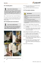
10.6  Mounting the pressure mandrel set


Fig. 8: Mounting the mandrel set

Step 1: Unscrew the piston head using the attached hex 

key.

Step 2: Insert the mandrel chuck into the piston chuck 

and tighten with the hex key.

Step 3: Insert the mandrel into the mandrel chuck.

10.7 Processing the workpiece

Step 1: Lock the support blocks on the press table.

Step 2: Position and/or secure the workpiece on the sup-

port blocks.

Step 3: Close both the valves 3 and 7 (Fig. 4) of hydrau-

lic pump (turn in clockwise direction) until they 
are closed completely.

Step 4: Operate the hand pump. The piston lowers.

Step 5: Release the hand/foot-operated pump once the 

hydraulic cylinder is over the workpiece.

Step 6: Align the workpiece and hydraulic cylinder.

Step 7: Open valve 3 and operate the hand pump to 

press the stamp onto the workpiece. Monitor the 
pressure gauge display.

Step 8: Close valve 3 (turn in anti-clockwise direction) 

after having processed the workpiece. The 
piston returns to its base position/standby posi-
tion.

Step 9: Remove the workpiece.

Tips and recommendations

The manufacturer has already configured the retract-
ing speed of the piston. Modifications are required or 
permitted following maintenance work or repairs only. 
For this reason, the adjusting screw has been cov-
ered.

Tips and recommendations

The optional pressure mandrel set is supplied with a 
chuck, pressure mandrels with different diameters 
and an Allen key for loosening and tightening the 
Allen screw on the piston of the press.

IMPORTANT!

-  Make sure the securing bolts have been installed 

correctly!

-  Make sure the workpiece has been centred under 

the piston! 

-  Do not exceed the press capacity! 

-  Do not use extensions for the pressure lever

-  Do not reach into the press and keep away from 

moving parts!

Summary of Contents for WPP 15 TE

Page 1: ...WPP 15 TE WPP 15 TE Operating Instructions Hydraulic workshop press WPP 15 TE...

Page 2: ...qualification 5 2 4 Personal protective equipment 5 2 5 Safety identifications on the workshop press 5 3 Intended use 6 3 1 Foreseeable misuse 6 3 2 Remaining risks 6 4 Technical data 6 4 1 Table 6 4...

Page 3: ...mit any information and experiences you make during application of the machine as these may be valuable for product improvements 1 3 Disclaimer All data in these operating instructions has been com pi...

Page 4: ...rating instructions they created meet current standards and adapt the op erating instructions where necessary Operators shall clearly manage and specify the re sponsibilities for installation operatio...

Page 5: ...f persons at work Staff must wear the personal protective equipment indicated in individual sections of these operating instructions when carrying out the different tasks on the machine The personal p...

Page 6: ...ess is ob served there is no actually foreseeable misuse that may cause hazardous situations involving personal injury 3 2 Remaining risks Even when observing all safety instructions operation of the...

Page 7: ...riveways ramps and the like are particularly dangerous If such passages are unavoidable special caution is required Before starting the transport check the transport route for possible danger points u...

Page 8: ...ne PE padding is made of polystyrene PS Dispose of these substances at a recycling centre or hand them over to the relevant waste disposal company Storage As a rule the hydraulic workshop press must b...

Page 9: ...ig 5 Installing crossbeam feet Step 1 secure the crossbeam feet and the two cross beams to both sides of the frame using the screws shims spring washers and nuts see Fig 5 Step 2 insert the support bo...

Page 10: ...s Step 3 Check all lines and connections are not leaking Check all machine parts are undamaged and op erate as intended 10 Operation WARNING Risk of death Non observance of these instructions causes a...

Page 11: ...1 For quick moving down the piston close both the valves 3 und 7 Fig 4 turn clockwise and move the pump lever Step 2 When the piston is positioned closed above the workpiece open valve 3 Fig 4 turn a...

Page 12: ...is over the workpiece Step 6 Align the workpiece and hydraulic cylinder Step 7 Open valve 3 and operate the hand pump to press the stamp onto the workpiece Monitor the pressure gauge display Step 8 Cl...

Page 13: ...e hydraulic pipes must be replaced after an operating period of six years In the event of increased usage peri ods and stricter requirements pipes must be replaced every two years 11 2 1 Oil changes D...

Page 14: ...he hydraulic pipes and connections checked by an authorised person In the event of increased usage periods frequent or increased pressure pulses or severe external influ ences the machine must be chec...

Page 15: ...required for queries or spare parts orders Device type Item number Spare parts drawing number Position number Year of manufacture Quantity Desired shipping type post freight sea air ex press Shipping...

Page 16: ...parts drawing The following drawing is intended to identify the required spare parts in the event of service If applicable submit a copy of the parts drawing including the highlighted components to yo...

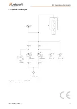
Page 17: ...EC Declaration of Conformity WPP 15 TE Version 1 06 17 13 3 Hydraulic Circuit diagram Fig 10 Hydraulic circuit diagram of the WPP 15 TE...

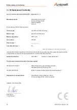
Page 18: ...type plate complies with all relevant regulations of the aforementioned directive as well as any other applicable directives subse quently added including the changes applicable at the time the declar...

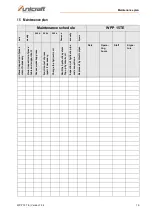
Page 19: ...s Visual inspection of press clean if necessary Visual inspection of press table and support bolt Grease workshop press Function test of press repair if necessary Change the hydraulic oil Vent the hyd...

Page 20: ...www unicraft de...

Reviews: