


Maintenance
- 85 -
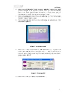
1. Prepare (Refer 7.6.1).
2. Press 3 to select “WL Scan”, press “F1” to setup, set the parameter as
follow, press “Enter” to finished setup.
Scan from: 400
Scan to: 300
Scan Step: 0.1
Scan Speed: HI
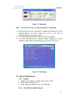
3. Ensure beam is clear. Press “0Abs” to scan blank.
4. Insert holmium filter. Press “Start”.
5. When scan complete, press “F3”: Search, Press “
▼
”, record wavelength
of holmium peak (specification: 360.9 ±1nm).
6. Press “ESC”, press “F1” to setup, set the parameter as follow, press
“Enter” to finished setup.
Scan from: 850
Scan to: 750
Scan Step: 0.1
Scan Speed: HI
7. Ensure beam is clear. Press “0Abs” to scan blank.
8. Insert didymium filter. Press “Start”.
9. When scan complete, press “F3”: Search, Press “
▼
”, record wavelength
of didymium peak (specification: 807.1 ±1nm).
7.6.3 Check Stray Light
1. Prepare (Refer 7.6.1).
2. Press
“Set
λ
”, input 340, press “Enter” to go to 340nm.
3. Ensure beam is clear. Press 1 to “Basic Mode” and automatic blanking.
4. Insert GG375 filter.
5. Record stray light at 340nm (specification >3A, <0.1%T).
6. Remove
filter.
7. Press
“Set
λ
”, input 220, press “Enter” to go to 220nm.
8. Insert WG295 filter.
9. Record stray light at 220nm (specification >3A, <0.1%T).
7.6.4 Check Absorbance Accuracy
1. Prepare (Refer 7.6.1).
2. Fit neutral density filters, blank, 0.5A, 1A, 2A in cell changer and move
blank into beam
3. Press
“Set
λ
”, input 546, press “Enter” to go to 546nm.
4. Push filters into beam and record values. Compare the results with the
calibrated absorbance (specification <±1%A, so <±0.005A at 0.5A,
<±0.010A at 1A, <±0.020A at 2A).
Summary of Contents for SQ Series
Page 5: ......
Page 8: ...Introduction 3 Figure 1 5 Model UV 4802...
Page 12: ...Layout 7 Figure 3 2 Layout of UV 2800 Inside Bottom View...
Page 13: ...Layout 8 39 40 41 42 43 Figure 3 3 Layout of UV 2800 Top View...
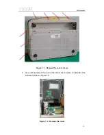
Page 14: ...Layout 9 230V 44 45 46 47 48 49 50 51 Figure 3 4 Layout of UV 2800 Back View...
Page 18: ...Layout 13 Figure 3 7 Layout of UV 2802 S UV 2802PC S Inside Bottom View...
Page 19: ...Layout 14 43 44 45 46 47 Figure 3 8 Layout of UV 2802 S Top View...
Page 20: ...Layout 15 230V Figure 3 9 Layout of UV 2802 S UV 2802PC S Back View...
Page 23: ...Layout 18 Figure 3 11 Layout of UV 3802 Inside Bottom View...
Page 24: ...Layout 19 44 45 46 47 48 Figure 3 12 Layout of UV 3802 Top View...
Page 25: ...Layout 20 230V Figure 3 13 Layout of UV 3802 Back View...
Page 28: ...Layout 23 Figure 3 14 Layout of UV 4802 Inside Top View...
Page 29: ...Layout 24 Figure 3 15 Layout of UV 4802 Inside Bottom View...
Page 30: ...Layout 25 43 44 45 46 47 Figure 3 16 Layout of UV 4802 Top View...
Page 31: ...Layout 26 230V Figure 3 17 Layout of UV 4802 Back View...
Page 35: ...Optical 30 Figure 4 3 Optical System schematic diagram of UV 4802...
Page 49: ...Electronic System 44 Figure 5 13 Layout of Main CPU PCB...
Page 63: ...Trouble Shooting 58 6 Trouble Shooting 6 1 Tungsten lamp off...
Page 69: ...Trouble Shooting 64 6 8 Slit check failed Only for UV 2802S UV 2802PCS...
Page 72: ...Trouble Shooting 67 6 13 Get dark current for a long time...
Page 74: ...Trouble Shooting 69 6 15 Backlight OK but display nothing on LCD Display...
Page 77: ...Trouble Shooting 72 6 18 No DC 12V on PCB SST8 412 113...