


Maintenance
- 79 -
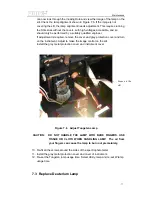
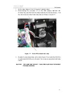
Figure 7.8 Deuterium Lamp
4. Reconnect the connector J7 to the PCB marked SST8.411.128.
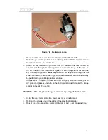
5. Re-fit the grey metal protection cover. Temporarily re-fit the main cover and
fix with two screws, one each side.
6. Switch on and remove the grommet from the middle of the rear panel. You
can now look through the Viewing Hole and view the image of the lamp on
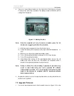
the slit. Check the lamp alignment Figure 7.9. If the image is not covering the
slit, the lamp alignment needs adjustment. This requires running the SQ
series without the covers, with high voltages accessible, and so should only
be performed by a suitably qualified engineer.
If adjustment is required, remove the cover and grey protection cover, put on
UV protection glasses and turn on the instrument. Adjust to make the image
central on the slit, Figure 7.9.
CAUTION: Wear UV protection glasses when replacing deuterium lamp.
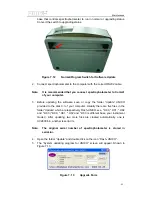
7. Install the grey metal protection cover and cover of instrument.
8. Re-fit all the screws around the sides of the spectrophotometer.
9. Re-set the lamp usage time. Select Utility, lamp, and re-set D2 usage time.
Summary of Contents for SQ Series
Page 5: ......
Page 8: ...Introduction 3 Figure 1 5 Model UV 4802...
Page 12: ...Layout 7 Figure 3 2 Layout of UV 2800 Inside Bottom View...
Page 13: ...Layout 8 39 40 41 42 43 Figure 3 3 Layout of UV 2800 Top View...
Page 14: ...Layout 9 230V 44 45 46 47 48 49 50 51 Figure 3 4 Layout of UV 2800 Back View...
Page 18: ...Layout 13 Figure 3 7 Layout of UV 2802 S UV 2802PC S Inside Bottom View...
Page 19: ...Layout 14 43 44 45 46 47 Figure 3 8 Layout of UV 2802 S Top View...
Page 20: ...Layout 15 230V Figure 3 9 Layout of UV 2802 S UV 2802PC S Back View...
Page 23: ...Layout 18 Figure 3 11 Layout of UV 3802 Inside Bottom View...
Page 24: ...Layout 19 44 45 46 47 48 Figure 3 12 Layout of UV 3802 Top View...
Page 25: ...Layout 20 230V Figure 3 13 Layout of UV 3802 Back View...
Page 28: ...Layout 23 Figure 3 14 Layout of UV 4802 Inside Top View...
Page 29: ...Layout 24 Figure 3 15 Layout of UV 4802 Inside Bottom View...
Page 30: ...Layout 25 43 44 45 46 47 Figure 3 16 Layout of UV 4802 Top View...
Page 31: ...Layout 26 230V Figure 3 17 Layout of UV 4802 Back View...
Page 35: ...Optical 30 Figure 4 3 Optical System schematic diagram of UV 4802...
Page 49: ...Electronic System 44 Figure 5 13 Layout of Main CPU PCB...
Page 63: ...Trouble Shooting 58 6 Trouble Shooting 6 1 Tungsten lamp off...
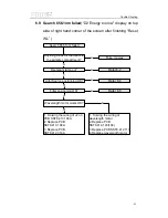
Page 69: ...Trouble Shooting 64 6 8 Slit check failed Only for UV 2802S UV 2802PCS...
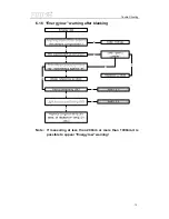
Page 72: ...Trouble Shooting 67 6 13 Get dark current for a long time...
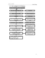
Page 74: ...Trouble Shooting 69 6 15 Backlight OK but display nothing on LCD Display...
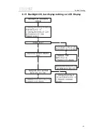
Page 77: ...Trouble Shooting 72 6 18 No DC 12V on PCB SST8 412 113...