UNIBLOC-PD Operation & Service Manual: PD501-576 15
4.0 Gearbox Maintenance and Service
The UNIBLOC gearbox is supplied with nitrile seals, drain plugs and an optional vent. The oil level should be checked at regular
intervals and the seals should be changed once per year or after 2000 hours of service, whichever occurs first. When applications
exceed constant service temperatures of 180°C (356°F) high temperature lubricant and seals must be used. For such cases, con-
tact Unibloc-Pump or an authorized service center for an adequate service schedule. Before proceeding with the following steps,
DISENGAGE POWER TO THE HYDRAULIC OR PTO MOTOR
. If the pump is connected to piping, depressurize the
system and close valves on both the suction and discharge sides to isolate the pump from the rest of the system. Disconnect the
piping and remove the pump from the system. If the pump is flange mounted to the motor, the pump must be unmounted before
servicing. Unmount the pump from the motor by removing the four bolts (9) from the motor flange.
Removal of the wet end of the pump (i.e. the cover, rotors, rotor housing, and shaft seals) must be completed first before disas
-
sembly of the pump gearbox. The method of removing these parts is dependent upon the type of shaft seals the pump has and is
outlined in section 3.
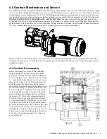
4.1 Gearbox Disassembly
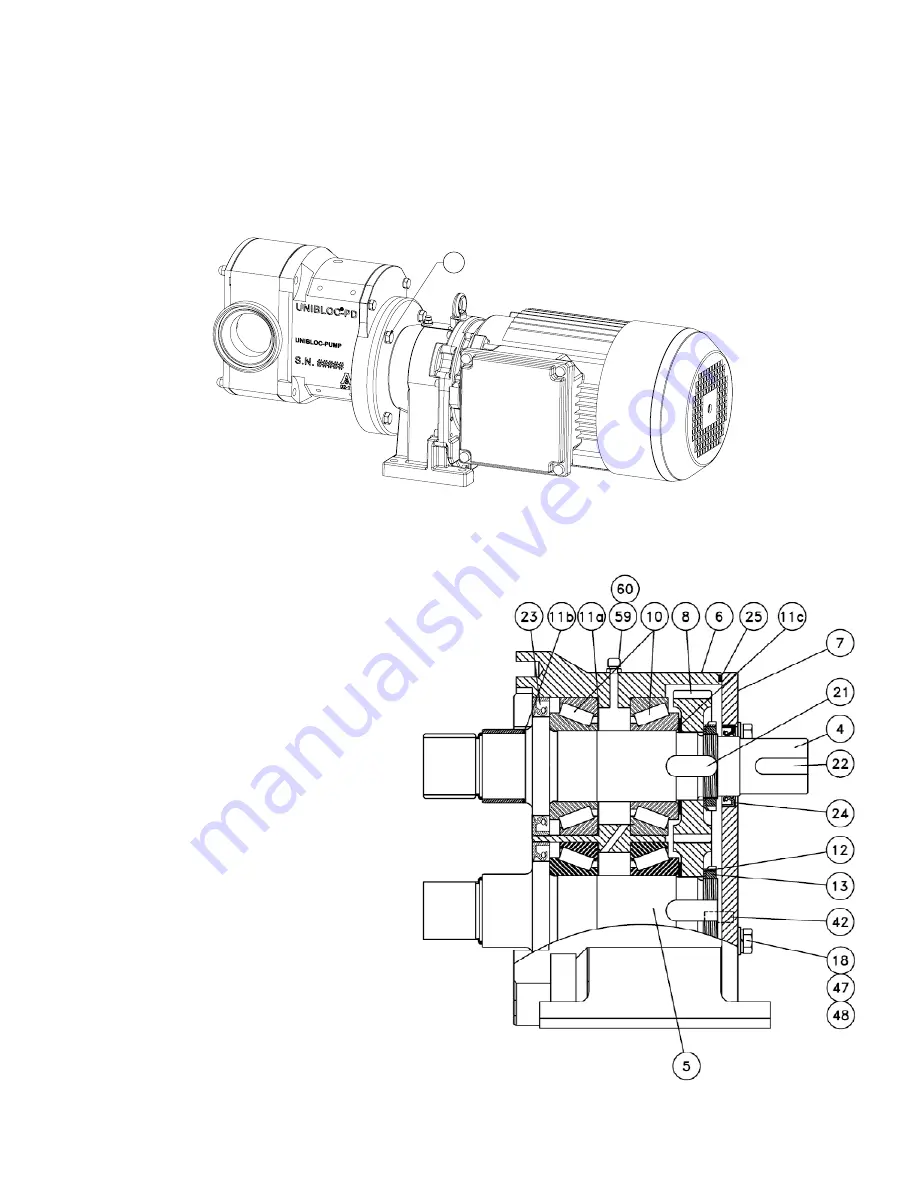
Remove the front cover, rotors, housing and shaft
seals as described in section 2. Drain oil from the
gearbox by removing the drain plug, if available, or
by removing the cover (7), PTO drive shown in figure
4.1. Open the tab on the tab washers (12) and remove
them and the slotted nuts (13). With a rubber mallet,
strike the ends of the shafts where the tab washers
were located to loosen the gears (8) and remove them.
Be sure not to damage the threads on the shafts. The
keys (21) will now be exposed and can be removed
with a flat tipped screwdriver. Continue striking the
shafts with the rubber mallet to push the shafts and
the oil seals (23), which will get damaged and will
have to be replaced, out of the gearbox. Each shaft
will have one bearing (10) located next to a shoulder.
To remove them, if necessary, do so with a hydraulic
press or tap with a punch or sleeve on the edge closest
to the shoulder. Use caution to prevent damage to the
shaft shoulder. Tap the bearing cups (10), in a circular
pattern to remove them from the gearbox. Behind one
of the cups (10) are the shim rings (11a) which can
now be removed.
Figure 4.1
9
Summary of Contents for UNIBLOC-PD 501
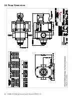
Page 26: ...26 UNIBLOC PD Operation Service Manual PD501 576 8 0 Pump Dimensions UNIBLOC PUMP ...
Page 27: ...UNIBLOC PD Operation Service Manual PD501 576 27 UNIBLOC PUMP ...
Page 28: ...28 UNIBLOC PD Operation Service Manual PD501 576 UNIBLOC PUMP ...
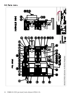
Page 30: ...30 UNIBLOC PD Operation Service Manual PD501 576 UNIBLOC PUMP 9 0 Parts Lists ...
Page 31: ...UNIBLOC PD Operation Service Manual PD501 576 31 UNIBLOC PUMP ...
Page 33: ...UNIBLOC PD Operation Service Manual PD501 576 33 3 ...
Page 34: ......
Page 35: ......

