UNIBLOC-PD Operation & Service Manual: PD501-576 13
3.2 Single Mechanical
TM
Seal
This seal comes with different seal face combinations. (See drawing G812B for details.) Maximum shaft rotational speed for this
seal is 2.4 m/s (7.8 ft/s) or 800 rpm and the maximum service pressure should not exceed 15 bar (220 psig). Maximum and mini-
mum temperature limits are +160°C (320°F) and -15°C (5°F).
3.2.1 Single Mechanical
TM
Seal Removal
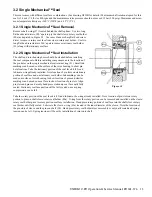
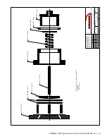
Remove shaft o-ring (27) located behind the shaft splines. Use two long
flat head screwdrivers 180° apart to pry the shaft sleeve/rotary seal holder
(80a) as depicted in Figure 3.2. Use razor blade or sharp flat head screw
-
driver to remove rotary seal face from sleeve/rotary seal holder. Use two
long flat head screwdrivers 180° apart to remove stationary seal holder
(91) along with stationary seal face.
3.2.2 Single Mechanical
TM
Seal Installation
The shaft and rotor housing bores should be cleaned before installing
the seal components. Before installing components, note the location of
the pin holes on the single mechanical seal retainer ring (91). Small ink
markings can be made on the surface of the rotor housing to show pin
hole locations. Take the stationary portion of the seal face kit (92) and
lubricate o-ring already installed. Note location of pin slots on stationary
portion of seal face and on stationary seal holder. Ink markings can be
made on surface of rotor housing to show location of pins and similar
markings can be made on seal face to show location of pin slots. Align
pin slots and pins and evenly hand press stationary seal face until fully
seated. Stationary seal face portion will be fully seated once a spring
compression can be felt.
Take the rotary portion of the seal face kit (92) and lubricate the o-ring already installed. Note location of pin slots on rotary
portion to pins on shaft sleeve/rotary seal holder (80a). O-ring from the rotary portion can be removed and installed on the sleeve/
rotary seal holder prior to rotary portion seal face installation. Hand press rotary portion of seal face into the shaft sleeve/rotary
seal holder until fully seated. Lubricate the sleeve o-ring (81a) located in the inner diameter of the sleeve. Note the location of
the pin slots of sleeve and the pins on shaft (90). Hand press rotary seal holder/sleeve assembly evenly until seated and spring
tension can be felt. Spring tension will be set by installation of rotor onto shaft.
Figure 3.2
Summary of Contents for UNIBLOC-PD 501
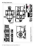
Page 26: ...26 UNIBLOC PD Operation Service Manual PD501 576 8 0 Pump Dimensions UNIBLOC PUMP ...
Page 27: ...UNIBLOC PD Operation Service Manual PD501 576 27 UNIBLOC PUMP ...
Page 28: ...28 UNIBLOC PD Operation Service Manual PD501 576 UNIBLOC PUMP ...
Page 30: ...30 UNIBLOC PD Operation Service Manual PD501 576 UNIBLOC PUMP 9 0 Parts Lists ...
Page 31: ...UNIBLOC PD Operation Service Manual PD501 576 31 UNIBLOC PUMP ...
Page 33: ...UNIBLOC PD Operation Service Manual PD501 576 33 3 ...
Page 34: ......
Page 35: ......

