UTD2000M
User
Manual
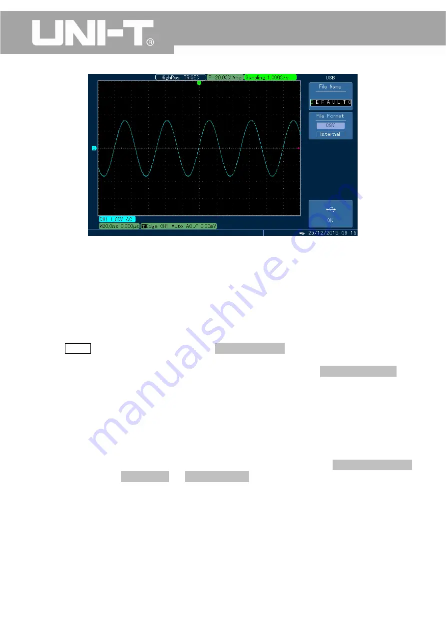
Fig.
3
‐
15
Save
the
waveform
into
U
‐
disk
Notes:
CSV
format
files
can
be
opened
by
EXCEL
in
scatter
diagram
form
or
by
MATLAB
software
for
further
analysis.
3.9
Pass/Fail
Detection
Detect
whether
or
not
the
input
signal
is
within
the
preset
scope,
it
fails
if
not,
otherwise
it
passes.
In
addition,
we
can
use
the
“Pass/Fail”
output
terminal,
located
behind
the
oscilloscope,
to
export
“Pass/Fail”
signal.
1.
Press
UTILITY
key
and
then
press
F3
to
enter
into
“pass
detection
menu”;
2.
Set
signal
source:
enter
into
P/F
TEST
(Pass
Detection)
menu
and
press
F3
to
set
signal
source.
3.
Template
Setting:
Press
F5
to
enter
into
next
page
and
then
press
F3
to
enter
into
template
setting
menu.
Press
F1,
and
then
select
reference
waveform
using
“MULTIPURPOSE”
knob.
Press
F3
and
F4,
and
then
set
horizontal
and
vertical
tolerance
by
using
“MULTIPURPOSE”
knob
(Horizontal:
1
‐
100
Pixel;
Vertical:
1
‐
100
Pixel).
After
that,
press
F5,
set
and
save
the
template,
and
return
to
Pass/Fail
menu.
4.
Set
output
condition:
Press
F5
to
return
to
the
first
page
of
“Pass/Fail”
menu.
Press
F2
to
set
the
“Pass/Fail”
port
(located
behind
the
oscilloscope)
and
the
judgment
condition
for
output
of
buzzer.
While
in
“Pass/Fail”
menu,
press
F1
to
open
the
“Detection”
State,
as
shown
in
Fig.
3
‐
13.
5.
Press
F4
key
to
set
whether
the
judgment
result
will
be
shown;
6.
Press
F5
key
to
enter
into
the
second
page
of
“Pass/Fail
menu”.
Press
F2
to
enter
into
stoppage
setting
menu:
Press
F1,
F2
key
to
set
stoppage
type
and
stoppage
condition.
Then
set
the
threshold
value
using
“MULTIPURPOSE”
knob.
Once
complete
the
setting.
Press
F5
to
return
to
the
“Pass/Fail”
menu,
as
shown
in
Fig.
3
‐
14.
7.
Press
F1
to
start
the
detection.
Once
the
instrument
is
in
operation,
press
F1
again
to
stop
it
manually.
Notes:
After
it
is
stopped
each
time,
the
count
of
“Pass/Fail”
times
will
be
started
all
over
again,
as
shown
in
Fig.
3
‐
15.
75


