User’s Manual and UT5320R-SxA Series
33 / 43
Instruments.uni-trend.com
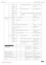
Figure 8-2 Time Sequency of HANDLER
Table 8-2 Time Sequency of HANDLER
Signal
Description
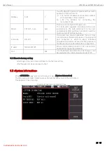
Use HANDLER interface to
start the test
1. Judge whether the TEST (under testing) signal on the interface is
valid. Only when the TEST (under testing) signal is invalid can the
START signal be received.
2. When meet the first rule is met, the test can be started by sending
START signal with a width of 40ms ~ 200ms (i.e. the closing time of
the switch quantity).
Use HANDLER interface to
stop the test
At any time, send the RESET signal with a width of 40ms ~ 200ms
(i.e. the closing time of the switching quantity) to stop the test.
Signal output—under testing
The relay will connect PIN2 and PIN5 when the instrument is
testing. After the test is completed, the relay will return PIN2 and
PIN5 to the open-circuit state.
Signal output—test is pass
When DUT test is pass, relay will connect PIN8 and PIN9 and hold
the state.
When other test program starts to test, or press the stop swith,
relay will return PIN8 and PIN9 to the open-circuit state.
Signal output—test is failed
When DUT test is failed, relay will connect PIN6 and PIN7 and hold
the state.
When other test program starts to test, or press the stop swith,
relay will return PIN6 and PIN7 to the open-circuit state.
All the input signals are input by switch value, other voltage or current source must not be connected.
If input other power, will cause the instrument internal control circuit damage or misoperation.
When the external control signal (signal output) needs to pass the voltage or current greater than
220V or 2A, the internal relay of the instrument will not be able to bear it. Please transfer it by yourself.


