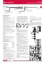
Mirage M-‐125 / M-‐115 Operating & Maintenance Instructions
4
2.2 Danger if Safety Instructions are Not Observed
Disregarding of the safety instructions may lead to harm of the user, bystanders,
environment and/or the product.
3.0 Description
The Mirage M-‐125 / M-‐115 shall be operating within the following pressure ranges:
•
Recommended operating pressure 45 -‐120 Psi (3 to 8 bar)
The maximum allowable operating pressure shall not exceed 145 Psi (10
bars).
4.0 Installation
Prior to installing the Mirage M-‐125 / M-‐115 sprinkler note the following installation
instructions:
1.
Flush the mainline and any sub-‐laterals thoroughly ensuring any rocks, sediment,
PVC burrs or other extraneous piping materials are no longer present in the piping
system.
2.
The sprinkler inlet threads are 1-‐1/2” BSP (British Standard Pipe).
3.
Seal threaded connections with Teflon tape only. Do not use Teflon paste or Pipe
Dope in addition to this product. Apply at least 5-‐7 wraps of Teflon tape to the
threaded male connection. Use caution, avoiding cross threading between mated
connections.
4.
Install the sprinkler in accordance with the prepared installation details using an
Underhill provided PVC or ductile iron swing joint assembly.
5.
Once the sprinkler head is installed, set vertically and to adjacent finish grade. Make
the wire connections (for valve-‐in-‐head models) using approved 3M DBRY
connections. Provide at least a 2-‐3’ long length of wire so sprinkler head can be
removed from the ground without having to cut or disconnect the control wire.
5.0 Commissioning
1.
Prior to operating the sprinkler with water, verify electrical actuation of the
sprinkler’s solenoid either from the control product previously installed or using a
“valve checker” by applying 24 VAC power to the control wires. An audible “click”
should be heard when power is applied to the valve solenoid verifying its operation.
2.
Pressurize the mainline and sub-‐laterals slowly. The sprinkler may open for a short
period of time (+/-‐ 30 seconds) but then should close on it’s own.
3.
Once the sprinkler head has closed on it’s own, check for leaks between the swing
joint and sprinkler head inlet threads.
4.
Confirm sprinkler arc pattern by operating the sprinkler rotating the drive assembly
back and forth manually. Adjust the left and right stops to confirm to the arc pattern
desired.
5.
Turning a small Torx screw within the interior of the sprinkler body will allow the
sprinkler to be turned on manually without electric actuation. See Figure 6-‐1.
WARNING!
WARNING!


