background image

(For dealer or factory use) 


1.  Press and hold  

 to 

enter Setup Page 
and tap 

 to select 

B9 icon. Tap


to 

enter System Unlock 
Page. 


2. 

Tap 

 or 

 and 


to input password. 


4.  Tap 

 to return to 

Main Page. 


Page 23


Summary of Contents for Mag 8e

Page 1: ...www undergroundmagnetics com Mag 8e System Manual ...

Page 2: ...7 4 Calibration 12 7 4 1 Depth Calibration 12 7 4 2 Roll Calibration 13 7 5 Operation 14 7 5 1 Depth Forecast 14 7 5 2 Transmitter Activation 16 7 5 3 Transmitter Settings 17 7 5 4 Receiver Settings 18 7 5 5 Radio Channel Selection 19 7 5 6 Pairing 20 7 5 7 Pitch Unit Selection 21 7 5 8 Depth Unit Selection 22 7 5 9 Time Setting 23 7 5 10 System Unlock 24 7 5 11 Contrast Adjustment 7 5 12 Speed Co...

Page 3: ...32 8 3 8 Distance Unit Selection 33 8 3 9 Contrast Adjustment 8 3 10 Communication Mode 8 4 Display Maintenance 35 9 Transmitter 36 9 1 Introduction 36 9 2 Specifications 36 9 3 Digital Information 37 9 4 Transmitter Maintenance 37 10 Locating Methods 38 10 1 Locating Basics 10 1 1 Three Point Locating 10 1 2 Single Point Locating 10 2 Bore To 11 Battery and Charger 56 12 Warranty 56 27 27 27 28 2...

Page 4: ...ntended to provide information and instructions on how to use this locating system properly Underground Magnetics Inc UM reserves the right to improve the locating system and the Operator s Manual at any time without notice Page 1 The transmitter sends digital information of the transmitter s pitch roll temperature and battery status through an FM modulated RF signal The receiver receives this inf...

Page 5: ... substances Wear proper personal protective equipment including steel toed boots safety gloves helmets reflective vests and safety goggles Obey all local safety regulations This locating system is only a tool to assist the operator to locate the drill head It is the operator not the Mag 8e locating system that is responsible for identifying the drill head location UM is not responsible for any dam...

Page 6: ...the instructions may cause harmful interference to radio communications However there is no guarantee that interference will not occur in a particular installation If this product does cause harmful interference to radio or television reception which can be determined by turning the equipment off and on the user is encouraged to try to correct the interference by one or more of the following measu...

Page 7: ... more detailed information for the corresponding steps The rest of the manual will contain detailed sections that follow the order of the Mag 8e Receiver and the Mag D8 menu screens It is recommended to read the whole Operator s Manual first Then use the separate Quick Start Guide which is included with your system as reference when needed Page References This question mark and textbox will tell y...

Page 8: ...1 2 5 4 3 Walk bore path and use depth forecasting to check for interference and select frequency Page 14 Install batteries into transmitter Install battery cap with provided battery cap tool Turn on display by holding power button until the Mag logo is visible on screen Page 43 Page 27 Install transmitter into the housing Turn on receiver by holding power button until the Mag logo is visible on s...

Page 9: ...center of housing If distance on receiver s screen reads anything other than 3m perform calibration Page 12 Begin drilling Page 12 Locate FLP Front Locate Point 9 Locate RLP Rear Locate Point 10 11 Locate LL Locate Line Repeat steps 9 through 11 as you continue to guide drill Page 45 Page 45 Page 45 Page 6 ...

Page 10: ...d plated electronic modules High performance DSP Dual locating system functioning as two receivers independently tracking to provide better accuracy and reliability Up to 360ft depth range and up to 120 hours continuous usage Display Mag D8 Receiver Mag 8e Transmitter Echo 50 Echo 90 Echo 110 Page 7 ...

Page 11: ...old to enter secondary page Tap from main page to enter Bore To mode Setup key Tap to enter calibration page return to main page Press and hold to enter setup page 11 System frequencies 4kHz 31kHz Water resistant IP65 Temperature range 20 to 60 C Telemetry 4 radio channels with range up to 900m Rechargeable lithium battery 12 5V Battery life Up to 50 hours Dimensions 68 5 x 13 x 30cm Weight 3 kg P...

Page 12: ...ion of signal to noise Transmitter temperature Flashing indicates transmitter is over heating Direct distance between transmitter and receiver Roll indicator Clock positions Pitch Point direction of transmitter Ball representation of Locate Point Representation of receiver location Locate Line ...

Page 13: ...To enter the Secondary Page press and hold Page 10 Radio channel Receiver battery status Transmitter model frequency and power ...

Page 14: ...tion B2 Transmitter settings B3 Receiver settings B4 Radio channel selection B5 Receiver and display pairing B6 Roll calibration B7 Pitch unit selection B8 Time setting B9 System lock unlock B10 Visibility control B11 System info B13 Distance unit selection B16 Speed Control B20 Information Page 11 ...

Page 15: ...et transmitter and receiver 3 meters apart from center of transmitter to inside edge of receiver s base as shown 10 or 20m should only be used when drilling at extreme depths 4 Tap to enter Calibration and Depth Forecast Page Always do 3m calibration first 5 Tap once to enter Calibration Page and twice more to begin calibration 8 Calibration complete 7 Tap to return to Main Page Page 12 Make sure ...

Page 16: ...position 2 Press and hold to enter Setup page and tap to select B6 icon 3 Tap to enter Roll Calibration Page and tap twice more to start roll calibration Wait for calibration to complete 4 Calibration complete 5 Tap to return to Main Page Page 13 ...

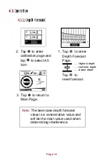
Page 17: ...5 icon 1 Tap to enter Depth Forecast Page 3 Tap to return to Main Page Note The best case depth forecast value is a conservative value and will be the main value used when determining interference Tap to reset forecast Highest depth real time depth lowest depth ...

Page 18: ...is highlighted Then tap to enter Transmitter Activation Page 3 1111 1111 is the transmitter identification number and 3333 3333 is the prompt code in the Page 15 4 Tap to return to Main Page diagram Send the transmitter identification number and the prompt code to the dealer The dealer will give you an activation password Use and to input a number and to move to the next number spot Tap once done ...

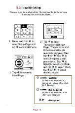
Page 19: ... Settings Page The receiver and Echo transmitter will automatically pair Then tap or and to select frequency and power level Tap to highlight Wake Up Mode and tap to enter Then tap or to select desired mode 3 Tap to return to Main Page Page 16 Instant rotate the transmitter 4 degrees or change the pitch by 1 degree 360 degrees rotate the transmitter a full 360 several times Always on ...

Page 20: ...1 Press and hold to enter Setup Page Tap to select B3 icon 2 Tap to enter Receiver Settings Page Tap or and to select transmitter model frequency and power 3 Tap to return to Main Page Page 17 ...

Page 21: ...1 Press and hold to enter Setup Page Tap to select B4 icon 2 Tap to enter Radio Channel Page Use or to select radio channel 3 Tap to return to Main Page Page 18 ...

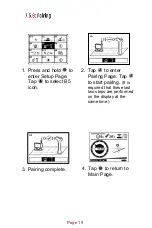
Page 22: ...r Setup Page Tap to select B5 icon 2 Tap to enter Pairing Page Tap to start pairing It is required that these last two steps are performed on the display at the same time 3 Pairing complete 4 Tap to return to Main Page Page 19 ...

Page 23: ...1 Press and hold to enter Setup Page and tap to select B7 icon Tap to enter Pitch Unit Selection Page 2 Tap to switch pitch mode 3 Tap to return to Main Page Page 20 ...

Page 24: ...Page 21 1 Press and hold to enter Setup Page Tap to select B13 icon 2 Tap to enter Distance Unit Selection Page Tap or to select unit and format 3 Tap to return to Main Page ...

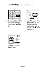
Page 25: ...er or factory use 2 Press and hold to enter Setup Page Tap to select B8 icon 3 Tap to enter Time Settings Page Tap to select year month day hour or minute Tap or to set time 4 Tap to return to Main Page Page 22 ...

Page 26: ... For dealer or factory use 1 Press and hold to enter Setup Page and tap to select B9 icon Tap to enter System Unlock Page 2 Tap or and to input password 4 Tap to return to Main Page Page 23 ...

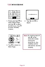
Page 27: ...tap to select the B10 icon Tap to enter Visibility Control 2 Tap and to adjust 3 Tap to return to Main Page Page 24 Note By holding both and at the same time while turning the receiver on the visibility control will reset to normal visibility ...

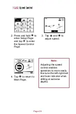
Page 28: ...ap to enter the Speed Control Page 3 Tap and to adjust speed 4 Tap to return to Main Page Page 25 Note Adjusting the speed control enables operators to more easily fine tune the left right ball and bore indicator when drilling at extreme depths ...

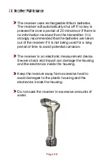
Page 29: ... batteries are taken out of the receiver if it is not being used for a long period of time to avoid potential corrosion The receiver is an electronic measurement device Severe shock and impact can damage the housing and the electronics inside the housing Keep the receiver away from excessive heat to avoid damages to the plastic housing and the electronics inside the housing Do not soak the receive...

Page 30: ...on Press and hold to enter secondary page Setup key Tap to return to main page Press and hold to enter setup page Radio frequency 433MHz Water resistant IP65 Temperature range 20 to 60 C Telemetry 4 radio channels with range up to 900m Power Rechargeable lithium batteries Battery life Up to 50 hours Screen Industrial rated LCD graphic display Dimensions 19 x 13 x 19 cm Weight 1 5kg Mag D8 Page 27 ...

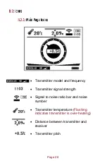
Page 31: ...nd frequency Transmitter signal strength Signal to noise ratio bar and noise number Transmitter temperature Flashing indicates transmitter is over heating Distance between transmitter and receiver Transmitter pitch Page 28 ...

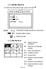
Page 32: ...n B5 Receiver and display pairing B7 Pitch unit selection B10 Visibility control B11 System info B12 Display communication mode B13 Distance unit selection B14 Down hole Echo mode change Page 29 Transmitter model frequency and power Display battery status Radio channel ...

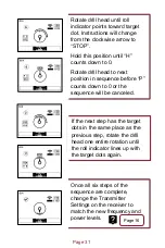
Page 33: ...se or to select desired frequency and power levels Tap to begin mode change process Roll indicator Target dot Hold hold this roll position until it counts down to 0 Steps remaining Instructions Proceed time left to proceed in process by rotating to new roll position in sequence Page 30 ...

Page 34: ...n sequence before P counts down to 0 or the sequence will be canceled If the next step has the target dots in the same place as the previous step rotate the drill head one entire rotation until the roll indicator lines up with the target dots again Once all six steps of the sequence are complete change the Transmitter Settings on the receiver to match the new frequency and power levels Page 16 Pag...

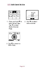
Page 35: ...1 Press and hold to enter Setup Page Tap to enter Radio Channel Page 2 Use to select radio channel 3 Tap to return to Main Page Page 32 ...

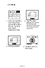
Page 36: ...age and tap to select B5 icon Tap to enter Radio Registration Page 2 Tap to start pairing It is required that the following procedure is performed on the receiver at the same time 3 Pairing complete 4 Tap to return to Main Page Page 33 ...

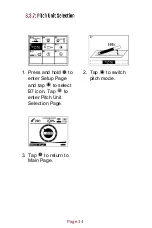
Page 37: ...1 Press and hold to enter Setup Page and tap to select B7 icon Tap to enter Pitch Unit Selection Page 2 Tap to switch pitch mode 3 Tap to return to Main Page Page 34 ...

Page 38: ...Page 35 1 Press and hold to enter Setup Page Tap to select B13 icon 2 Tap to enter Distance Unit Selection Page Tap or to select unit and format 3 Tap to return to Main Page ...

Page 39: ...p to select the B10 icon Tap to enter Visibility Control Page 2 Tap and to adjust 3 Tap to return to Main Page Note By holding both and at the same time while turning the receiver on the visibility control will reset to normal visibility Page 36 ...

Page 40: ... to enter Setup Page and tap to select B12 icon Tap to enter Communication Mode Page 2 The default communication mode will be wireless communication 3 Press to switch to cable mode 4 Tap to return to Main Page Page 37 ...

Page 41: ... batteries are taken out of the display if it is not being used for a long period of time to avoid potential corrosion The display is an electronic measurement device Severe shock and impact can damage the housing and the electronics inside the housing Keep the display away from excessive heat to avoid damages to the plastic housing and electronics inside the housing Do not submerge the display in...

Page 42: ...Hz 28kHz 30kHz or 31kHz The transmitter will enter a sleep mode after 15 minutes without rotation It takes 10 seconds to wake up once the transmitter is rotated Note If drilling in adverse soil conditions i e rock normal C cell batteries will experience battery chatter This can greatly reduce battery life To prevent this use your provided double C lithium cell battery instead Page 39 ...

Page 43: ... of continuous usage Temperature Under 88 C Weight 0 7 kg Dimensions 3 175 x 38 cm length Frequency 4kHz 19kHz 30kHz Depth Range 27 5m 40m 40m Power Echo Cell Kit or Lithium Battery Echo Cell Kit 3V 20 hours of continuous usage Lithium 3V 48 hours of continuous usage Temperature Under 88 C High Power Modes 19kHz and30kHz depth range of 160ft Operating time is 5 hours for Echo Cell Kit and 12 hours...

Page 44: ... battery 18650 3 7V Normal power 20 hours High power 5 hours 261020 3 7V Normal power 60 hours High power 15 hours Battery Voltage 2 8V 4 2V Dimensions 3 6 X 45 7 cm length Frequency 10 frequencies 4kHz 31kHz Depth Range Normal power 70m High power 90m Power 2 18650B2 rechargeable lithium batteries 18650B2 3 7V Normal power 80 hours High power 20 hours Battery Voltage 5 6V 8 4V Page 41 ...

Page 45: ... 3 18650B2 rechargeable lithium batteries 18650B2 3 7V Normal power 120 hours High power 30 hours Battery Voltage 8 4V 12 6V Dimensions 2 54 x 20 32 cm length Frequency 30kHz Depth Range 18 5m Power 1 18650 rechargeable lithium battery Roll 24 transmitter roll positions Pitch 0 1 resolution Temperature Under 88 C Battery Voltage 3V Page 42 ...

Page 46: ...tter is overheating temperature indication in the receiver s display flashes If temperature reaches over 121 C transmitter may be permanently damaged If this happens the dot temperature indicator on the front of transmitter will turn black Do not place the transmitter near excessive temperature over 250 F 121 C Do not apply excessive pressure shock or vibration on the transmitter Take the battery ...

Page 47: ... locate point FLP ahead of the transmitter the rear locate point RLP behind the transmitter and the locate line LL above the transmitter For the most accurate location and depth of the transmitter both the FLP and the RLP should be located before locating the LL The front and rear locate points when lined up indicate the exact direction of the transmitter If the transmitter is level the locate lin...

Page 48: ...ll in the box Then imagine a line that runs through the FLP and RLP Walk along that line until the LL indicator on the receiver screen enters the box You are now above the LL Next find the RLP The RLP is a point behind the transmitter Locate it by putting the ball in the box Page 45 ...

Page 49: ... that the ball has a line on top This is the point in Single Point The line points in the direction that the transmitter is pointing in You now have the location of the FLP and the direction of the transmitter Switch to Bore To mode walk a bore s length forward in line with the point and wait for the FLP to come to you Continue moving forward and locating the FLP to locate with just a single point...

Page 50: ...receiver and the remote display will look like the screen to the right Bore head Transmitter Receiver Depth over the head Horizontal distance from transmitter to receiver Page 47 Projected depth Projected Depth Projected depth tells you what depth the head will be at when it reaches the receiver if the operator maintains the indicated pitch ...

Page 51: ... To mode Expose and verify visually while crossing utilities For best Bore To results the operator should locate up to the area that can t be walked over and mark both the FLP and RLP before moving the receiver to the other side Once on the other side place the receiver directly in line and proceed with drilling using the right left steering bar to keep the bore path in line It is best to place an...

Page 52: ...res will shorten the battery life Do not submerge the battery in water or any other liquids Do not throw the battery into fire Do not disassemble the battery Avoid any kind of damage to the battery Please dispose of lithium properly When charging the battery the red light will shine When charging is complete a green light will shine Underground Magnetics offers standard warranty on parts and labor...

Page 53: ...www undergroundmagnetics com ...

Reviews: