OPERATING INSTRUCTIONS
USER MANUAL — 74-36103-ENG R6
27
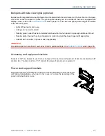
Bumpers with side view lights (optional)
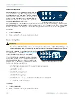
Bumpers with integrated side view light system are located at both foot end corners of the bed. Foot end bumpers
offer a 3/4" socket to support IV poles. The green lights intensity can be controlled if the bed is equipped with
display screen; refer to the
footboard control
section (page 35). The side view light system will give the status
of the bed exit system:
• lights off: bed exit is not in use
• solid green: bed exit is armed
•
flashing green: patient has been detected and bed will arm when patient is properly positionned in bed
•
flashing amber: bed exit has been triggered or motion interrupt has been triggered (if applicable)
• solid amber: bed exit is in pause mode (if applicable)
IMPORTANT
An audible signal can also be set; see bed exit control system settings in the
Footboard control
section (page 35).
Accessory and equipment sockets
Sockets of 3/4" are located in each corner bumper of the bed and, at head end of bed are located two 5/8”
sockets, two 1” sockets and two 1 1/2” sockets for usage of accessory or equipment.
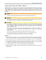
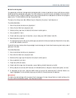
Power cord support brackets
Support brackets are available at the head end of bed (illustrated) to store the power
cord during transportation, when bed is not in use or to store the remaining of the
power cord when bed is in use.
Summary of Contents for ook cocoon
Page 1: ...2 0 1 7 0 8 7 4 3 6 1 0 3 E N G R 6 User manual FL36...
Page 2: ......
Page 3: ...2 0 1 7 0 8 7 4 3 6 1 0 3 E N G R 6 User manual FL36...
Page 22: ......
Page 50: ......
Page 62: ......
Page 74: ......
Page 78: ......

