- 6 -
Motor ; Single phase, 100V 50/60Hz,110V 60Hz 550W, 4Poles,
capacitor start and run
Weight ; 29.4kg
Motor ; three phase, 200V 50/60Hz,220V 60Hz, 700W, 4Poles
Weight
;
27.0kg
Fig. 3 Dimensional drawing of GCD-201X oil sealed rotary vacuum pump
Page 1: ...Before using the product be sure to read this manual Keep this manual in a place where it can be referred to at any time and look after it carefully The contents of this instruction manual are subjec...
Page 2: ...as not been damaged in transportation etc In order to use the pump for as long as possible read this instruction manual thoroughly before performing installation operation inspection and maintenance a...
Page 3: ...mishandled there is an imminent danger of the operator suffering a fatal accident or serious injury When mishandled there is a possibility of the operator suffering a fatal accident or serious injury...
Page 4: ...air always turn off the power switch Failure to do so may result in electric shock or the unexpected start of the pump leading to injury Connect the earth wire correctly It is recommended that a dedic...
Page 5: ...in operation Failure to do so will result in injury Never place combustible materials around the motor or pump There is a risk of fire Also do not place objects which block ventilation around the moto...
Page 6: ...cal Ammonia Acetone Ethylene oxide Ethylene diamine Zinc acetate Amyl acetate Aluminum acetate Isopropyl acetate Ethyl acetate Lead acetate Calcium acetate Cellosolve Acetate Nickel acetate Butyl acet...
Page 7: ...ative humidity 7 40 85 RH or less Height above sea level during storage and installation 1 000 m or less Other conditions for storage and operation a Free from corrosive and explosive gases b No conde...
Page 8: ...Data Sheet SDS 2 2 Outline of the Pump 3 2 1 Specification 3 2 2 Dimensional drawing 4 3 Installation 7 3 1 Installation 7 3 2 Lubrication 7 3 3 Vacuum piping 9 3 4 Electric wiring 10 3 4 1 GCD 051X 1...
Page 9: ...0 6 2 Periodic inspection 20 6 3 Replacement of the pump oil 22 6 4 Replacement of the coupling spider 24 6 5 Trouble check list 25 7 Disposal 27 8 Maintenance prats 28 8 1 Maintenance parts list 28 8...
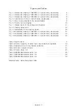
Page 10: ...ed curve 19 Fig 9 Replacement of the coupling spider 24 Fig 10 Disassembly drawing of GCD 051X oil sealed rotary vacuum pump 31 Fig 11 Disassembly drawing of GCD 136X oil sealed rotary vacuum pump 32...
Page 11: ...mp or harmful substances attached to the pump during inspection or disposal Wear protective equipment suitable for toxic substances when carrying out inspection Before overhauling and disposing of the...
Page 12: ...he surface temperature is hot touching the surface accidentally may result in burns Never touch the pump during operation When carrying out inspection wait until the pump has cooled down completely af...
Page 13: ...hase 5 6 100V 4 8 100V 5 1 110V 5 6 100V 5 4 100V 5 1 110V 7 5 100V 7 2 100V 7 0 110V Full load current A 3 phase 1 9 200V 1 8 200V 1 7 220V 3 5 200V 3 0 200V 2 9 220V 1 phase 1 440 100V 1 730 100V 1...
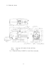
Page 14: ...4 2 2 Dimensional drawing Motor Single phase 100V 50 60Hz 110V 60Hz 200W 4Poles Weight 14 1kg Fig 1 Dimensional drawing of GCD 051X oil sealed rotary vacuum pump...
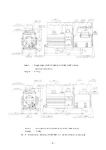
Page 15: ...phase 100V 50 60Hz 110V 60Hz 400W 4Poles capacitor start and run Weight 25 4kg Motor three phase 200V 50 60Hz 220V 60Hz 400W 4Poles Weight 22 8kg Fig 2 Dimensional drawing of GCD 136X oil sealed rota...
Page 16: ...phase 100V 50 60Hz 110V 60Hz 550W 4Poles capacitor start and run Weight 29 4kg Motor three phase 200V 50 60Hz 220V 60Hz 700W 4Poles Weight 27 0kg Fig 3 Dimensional drawing of GCD 201X oil sealed rota...
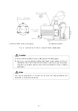
Page 17: ...own in Fig 1 2 3 3 2 Lubrication Remove the lubrication plug from the lubrication port and add the pump oil which has been delivered together with the pump or the pump oil specified by us SO M up to t...
Page 18: ...gles Be sure to read the attached Safety Data Sheet before adding oil If the oil accidentally comes into contact with your hands or enters your eyes take proper measures in accordance with the section...
Page 19: ...um chamber and pump as shown in Fig 5 Fig 5 Basic piping diagram to the vacuum chamber 3 Use a KF 25 NW 25 flange for the connection to the inlet pipe The wire mesh in the inlet pipe has been adopted...
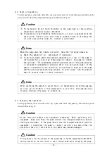
Page 20: ...el gauge side and will be rotated clockwise When you rotate in the opposite direction please shut off a power supply immediately replace wiring connected to U and W and check rotating in the right dir...
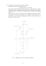
Page 21: ...and to the voltage change and frequency change in Domain B it shall operate with main rated values and shall be used practically convenient However operation with it is convenient and safe is maintain...
Page 22: ...rrectly Failure to do so may result in electric shock if a failure or earth leakage occurs Installation of a dedicated earth leakage breaker is also recommended Perform electric wiring correctly in ac...
Page 23: ...quency of the pump oil should be decided based on the contamination level of the pump oil If the pump evacuate a lot of moisture replace the oil frequently If the pump is used with gas which contains...
Page 24: ...using the pump If the pump is restarted in this condition an overload is applied to the pump and the overload protector may actuate In such a case turn the pump on and off several times in short inte...
Page 25: ...cylinder making restart difficult or causing damage to the pump The pump oil also may flow back to the vacuum chamber side see Fig 5 If vacuum valve A is not closed air may leak into the device side t...
Page 26: ...vacuum valve A and continue operation see Fig 5 If the temperature is low a satisfactory gas ballast effect is not achieved If the gas ballast valve is left open when condensable gas is not evacuated...
Page 27: ...to the instruction manual for the oil mist separators 4 9 Restriction on operation when the oil mist separators is installed When using the oil mist separators there are some restrictions on operatio...
Page 28: ...and rust on the inside walls of the pump and piping Gasifying of volatile components which have dissolved in the pump oil Deterioration of pump oil Existence of a gas supply source including vacuum l...
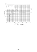
Page 29: ...19 Fig 8 Pumping speed curve...
Page 30: ...ot turn it on while inspection is in progress Doing so will result in injury The pump is very hot immediately after it is stopped Wait for a while until the pump has cooled down completely and then st...
Page 31: ...plugs Replace seals or contact us Evacuation wire mesh Clogged with dust Clean the wire mesh Once 3 000 operation hours or once 6 months Oil Even if no problem is recognized be sure to replace the oi...
Page 32: ...vice department to overhaul the pump always write the type of the vacuumed gas on the Pump Usage Check Sheet attached at the back of this manual and submit it Note that if toxic gases are exhausted bo...
Page 33: ...the pump inlet pipe to the atmosphere and operate the pump for five seconds The oil remaining in the pump is discharged efficiently 2 Remove the outlet pipe and drain plug to discharge the pump oil 3...
Page 34: ...ur bolts which fix the motor to the pump main unit and remove the motor Then the coupling can be removed and the spider taken out After inspecting the spider mount the spider to either of the two coup...
Page 35: ...he pump does not rotate Components inside the pump have burnt out Overhaul replace the damaged components Problem with power supply voltage Set the power supply voltage to within 10 of the rated volta...
Page 36: ...ormal sound is generated Components inside the pump have burnt out Overhaul replace the damaged components Continuous operation at high evacuation pressure If continuous operation is performed at a hi...
Page 37: ...osal of the pump When a harmful toxic gas has been exhausted ask a specialist for waste disposal Not only the pump itself but also the pump oil become toxic For the disposal of pump oil follow the ins...
Page 38: ...20 4 1 54 O ring _S 3 2 55 O ring _S 5 1 56 O ring _S 12 2 57 O ring _S 20 1 58 O ring _S 29 1 59 O ring _S 46 1 60 O ring _S 55 1 61 O ring _P 10 1 62 O ring _P 12 1 63 O ring _P 20 1 64 O ring _P 24...
Page 39: ...ring _S 30 2 72 O ring _S 45 1 73 O ring _S 70 4 74 O ring _G 55 1 75 O ring _V 175 1 76 O ring _JASO3056 1 77 O ring _N 28 2 GCD 136X Maintenance kit A 109 O ring _P 12 5 1 14 1st vane 2 15 2nd vane...
Page 40: ...ring _S 30 2 69 O ring _S 45 1 70 O ring _S 70 4 71 O ring _G 55 1 72 O ring _V 175 1 73 O ring _JASO3056 1 74 O ring _N 28 2 GCD 201X Maintenance kit A 104 O ring _P 12 5 1 14 1st vane 2 15 2nd vane...
Page 41: ...31 8 2 Disassembly drawing Fig 10 Disassembly drawing of GCD 051X oil sealed rotary vacuum pump...
Page 42: ...32 Fig 11 Disassembly drawing of GCD 136X oil sealed rotary vacuum pump...
Page 43: ...33 Fig 12 Disassembly drawing of GCD 201X oil sealed rotary vacuum pump...
Page 44: ...odifications or repairs carried out by a party other than the manufacturer or by a service company not approved by the manufacturer e Malfunctions caused by noise electric disturbance f Malfunctions t...
Page 45: ...fety and Health Law designates particular substances as the materials to be notified 2 Usage Status Operation Method Approx hours per day years and months Continuous Operation Intermittent Operation U...