- 9 -
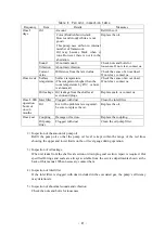
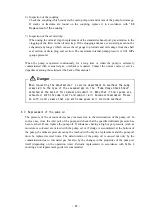
3.4 Electric wiring
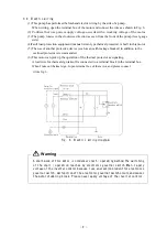
(1) This pump has performed beforehand electric wiring by the side of a pump.
When wiring, open the terminal box of the motor and connect the wires as shown in Fig. 6.
(2)
Confirm that use power supply voltage accords with a working voltage of the motor.
(3) The pump rotates in the clockwise direction as seen from the front of the pump (level gauge
side).
(4)Fault load protection equipment (manual return type thermal protector) is built in this motor.
(5) The use of another protective device (such as an earth leakage breaker) in addition to the
overload protector is recommended.
(6) This motor can pick up the operation of the thermal protector as signaling.
A lead wire for thermal sign takeoff is connected to a terminal block in the terminal box.
When I take out thermal sign, I open terminal box of the motor, and please connect
it like fig. 6.
Fig. 6 Electric wiring diagram
A start mode of this motor is condenser start / operating method.The switching
of the start / operation reaches by electronic governor switch.When I apply
voltage of the inverter control because I use an electron element for electronic
governor switch, malfunction of the electronic governor switch occurs and causes
the motor stumbling-block. Please never apply voltage of the inverter control.
Warning


